120 SA-1110 Developer’s Manual
Memory and PC-Card Control Module
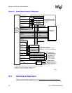
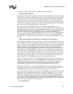
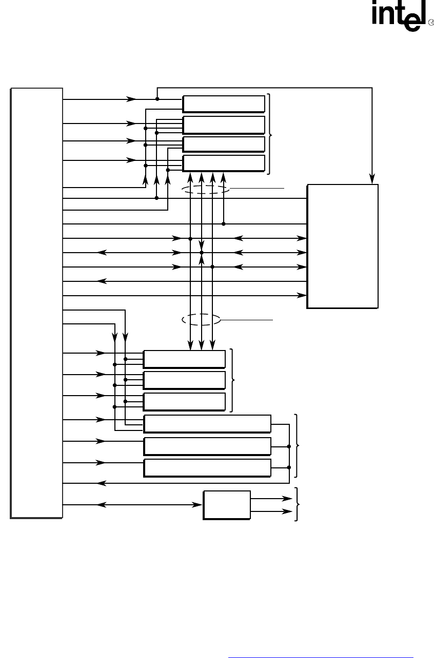
Figure 10-1. General Memory Interface Configuration
10.1 Overview of Operation
There is an online memory configuration tool at http://appzone.intel.com/hcd/sa1110/memory
which can be used to help configure the SA-1110 for operation with the user’s choice of memory.
A9187-01
DRAM Bank 0
DRAM Bank 1
DRAM Bank 2
DRAM Bank 3
nRAS/nSDCS<0>
nRAS/nSDCS<1>
nRAS/nSDCS<2>
Dynamic Memory Interface
Up to 4 banks of FPM, EDO,
or SDRAM memory (16-bit or
32-bit wide)
nRAS/nSDCS<3>
Static Bank 0
Static Bank 1
Static Bank 2
nCS<0>
nCS<1>
nCS<2>
nCAS/DQM<3:0>
Socket 0
Socket 1
D<31:0>
RDY
nSDRAS, nSDCAS
Buffers and
Transceivers
A<25:0>
PCMCIA
Control
Intel
®
StrongARM
*
SA-1110
Memory
Controller
Interface(3)
Static Memory Interface(2)
Up to 3 banks of ROM, Flash, SRAM or
SMROM(1) memory (16-bit or 32-bit wide)
Static / Variable Latency I/O Bank 3
nCS<3>
nCS<4>
nCS<5>
Static Memory or
Variable I/O Interface
Up to 3 banks of ROM,
Flash, SMROM(1) or
SRAM-like variable
latency I/O devices
(16-bit or 32-bit wide)
PCMCIA Interface
Up to 2-socket support.
Requires external logic to
complete the interface.
Refer to section 10.7.2.
Static / Variable Latency I/O Bank 4
Static / Variable Latency I/O Bank 5
1. SMROM width is required to be 32 bits and it is supported only on nCS<3:0>
2. Static Bank 0 must be populated by "bootable" memory.
3. RD/nWR, nOE, nWE are not shown in this figure.
SDCKE 1
MBREQ
MBGNT
SDCKE 0
SDCLK 1
SDCLK 2
SDCLK 0
Alternate Bus
Master
All DRAM banks
All static banks


