


SA-1110 Developer’s Manual 275
Peripheral Control Module
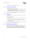
Case 3: EP0 Control Write (e.g. Set Descriptor)
1. At the beginning of the program, software initializes the internal state machine to
WAIT_FOR_SETUP.
2. Host sends a SETUP command.
3. SA-1110 UDC generates an EP0 Interrupt.
4. The software then determines the UDCCS0-OPR is set - 0000 0001b.
5. This indicates that a new OUT packet is in the EP0 Buffer identifying a SETUP transaction. To
help track this, software uses its state machine, which is currently WAIT_FOR_SETUP.
6. Software reads into a local buffer an amount of data from the UDCD0 Data Register FIFO as
specified by UDCWC-WC bits. To read the data: a) read the UDCWC-WC bits, b) read
UDCCD0, c) re-read the UDCWC-WC bits, and d) keep reading UDCCD0 followed by the
UDCWC-WC bits until the UDCWC-WC bits decrement. Software keeps reading the
UDCWC register until the UDCWC-WC bits indicate a count of 8 bytes.
7. When parsing the data in the buffer, software recognizes this is a Control Write command like
Set Descriptor and sets the internal state machine to DATA_STAGE_RCV. The software clears
the UDCCS0-OPR bit by writing a 1 to the UDCCS0-SO bit. The UDCCS0 register should
now be 0000 0000b.
8. To allow for a premature status stage, software loads a zero length packet into the transmit
FIFO by setting the IPR bit.
9. Return from interrupt.
10. The Host then issues an OUT packet, and the SA-1110 UDC issues an EP0 interrupt.
11. Upon entering the ISR, software sees the UDCCS0-OPR bit set - 0000 0001b. Software will
have to examine its internal state machine and see that it is in the state DATA_STAGE_RCV
and needs to receive more data.
12. Software reads the amount of data from the UDCD0 register determined by the UDCWC-WC
bits into a local buffer and clears the UDCCS0-OPR bit. The UDCCS0 register should now be
0000 0000b. Software continually monitors the UDCWC-WC for every byte read making
sure that the byte was transferred before reading the next byte.
13. Return from interrupt.
14. Go back to step 10 until all of the data is received.
15. When the last packet is received from the Host, the software then parses the command data
and performs the required setup, e.g. setting descriptor data. The software tracks how many
bytes were received by comparing it to the wLength field of the original SETUP packet.
16. The software then simultaneously clears the UDCCS0-OPR and sets the UDCCS0-DE bits.
The UDCCS0 register should now be 0001 0000b. The software sets its state machine to
WAIT_FOR_STATUS.
17. Return from interrupt.
18. When the Host executes the STATUS stage (OUT Packet), the SA-1110 UDC clears the
UDCSS0-DE bit and issues an EP0 interrupt.
19. Upon entering the ISR, the software then examines its internal state machine which is
WAIT_FOR_STATUS. When it sees the UDCCS0-SE bit is set, software clears the bit by
writing to the UDCCS0-SSE bit and sets its internal state machine back to
WAIT_FOR_SETUP.