SA-1110 Developer’s Manual 181
Memory and PC-Card Control Module
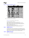
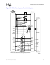
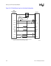
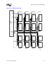
Figure 10-20. PC-Card External Logic for a Two-Socket Configuration
A6659-01
D(15:0)
GPIO(w)
GPIO(x)
GPIO(y)
GPIO(z)
PSKTSEL
A(25:0)
nPREG
nPWAIT
nPIOIS16
nPCE(1:2)
nPOE,
nPWE
nPIOW,
nPIOR
Intel
®
StrongARM
®*
SA-1110
D(15:0)
CD1#
CD2#
RDY/BSY#
WAIT#
WAIT#
IOIS16#
A(25:0)
REG#
CE(1:2)#
OE#
WE#
IOR#
IOW#
Socket 0
D(15:0)
Socket 1
DIR
nPCEx
nPCEx
nPOE
nPIOR
OE#
DIR OE#
RDY/BSY#
CD1#
CD2#
A(25:0)
REG#
CE(1:2)#
OE#
WE#
IOR#
IOW#
IOIS16#
WAIT#
6 6
6
WAIT#
Note: For pull-up resistors shown in this figure, recommend 10K ohm
resisters connected to socket/card supply voltage.


