


342 SA-1110 Developer’s Manual
Peripheral Control Module
11.12 Serial Port 4 – MCP / SSP
Serial port 4 contains two separate full-duplex synchronous serial interfaces. The multimedia
communications port (MCP) provides an interface to the Philips UCB1x00 codecs. These devices
have an audio codec, a telecom codec, a touch-screen interface, four general-purpose
analog-to-digital converter inputs, and ten programmable digital I/O lines. The MCP interface is
used by the SA-1110 both to input and output digital data to and from the codec, and to configure
and acquire status information from the codecs’ 16 registers. The synchronous serial port (SSP) is
used to interface to a variety of analog-to-digital converters, audio and telecom codecs, memory
chips, and keypad controllers as well as other miscellaneous serial devices. The SSP supports the
National Microwireand Texas Instruments synchronous serial protocols as well as a subset of the
Motorola serial peripheral interface (SPI) protocol.
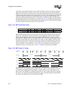
In MCP mode, serial port 4 controls communication between the SA-1110 and either the UCB1x00
codecs. The MCP produces two 64-bit subframes per frame (totalling 128 bits per frame) using a
bit clock and frame synchronization signal. Data is communicated full-duplex via a separate
transmit and receive data line. Selecting the on-chip clock, a bit clock frequency of either 9.585
Mbps or 11.981 Mbps can be programmed. Alternatively, GPIO pin 21 can be used to input a bit
clock from an off-chip source. This feature allows users to select a frame rate that is an exact
multiple of the desired audio/telecom sample rate. The MCP communicates to the codec in the first
of the two subframes. The second subframe is used in high-end applications to communicate with a
second stereo codec; however, this feature is not supported by the MCP. Subframe 0 contains seven
different fields of information. These fields include: audio conversion data, telecom conversion
data, data valid flags, control register address, control register data, and read/write control. Both
transmit and receive frames contains these seven fields. The transmit frame contains data for
D-to-A conversion as well as address, data, and control signals to write to or read from the codec’s
registers, and the receive frame contains A-to-D samples and the data returned from a read of a
codec register.
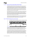
Both the MCP and the off-chip codec contain programmable 7-bit divisors, one each for the
telecom and audio data. These values are used to divide the bit clock to generate a desired sampling
frequency. When the codec is enabled, the divisor pairs are synchronously transferred to their
respective modulus registers within the MCP and off-chip codec, and decrement using the bit
clock. This technique allows telecom and audio data with different sampling frequencies to be
transferred between the MCP and codec, lock-step in sync with the sampling/conversion frequency
of the codec.
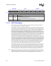
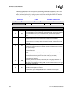
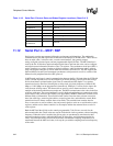
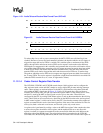
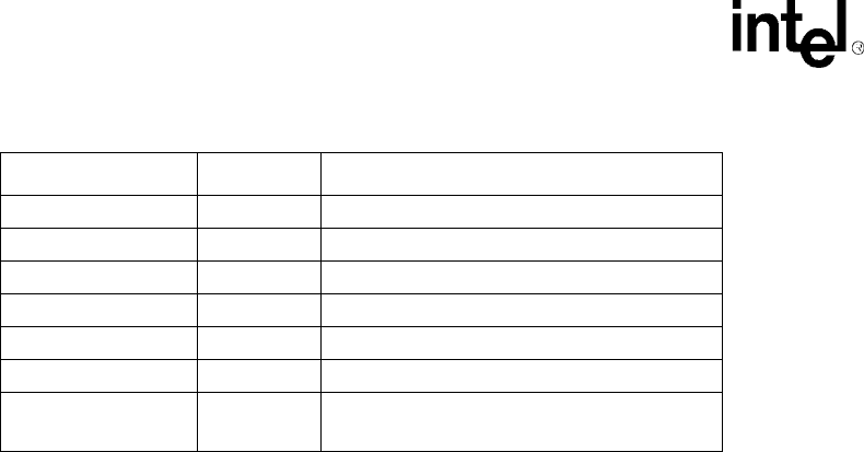
0h 8005 000C UTCR3 UART control register 3
0h 8005 0010 — Reserved
0h 8005 0014 UTDR UART data register
0h 8005 0018 — Reserved
0h 8005 001C UTSR0 UART status register 0
0h 8005 0020 UTSR1 UART status register 1
0h 8005 0024 –
0h 8005 FFFF
— Reserved
Table 11-19. Serial Port 3 Control, Data, and Status Register Locations (Sheet 2 of 2)
Address Name Description