


SA-1110 Developer’s Manual 237
Peripheral Control Module
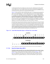
11.7.4.1 Pixels Per Line (PPL)
The pixels per line (PPL) bit-field is used to specify the number of pixels in each line or row on the
screen. PPL is a 10-bit value that represents between 16 and 1024 pixels per line. PPL is used to
count the correct number of pixel clocks that must occur before the line clock can be asserted. The
user should program PPL with the desired number of pixels per line minus 16. Note that the bottom
four bits of PPL are not implemented and therefore are not writable. Reads of these bits return
zeros because the LCD controller only supports displays that are a multiple of 16 pixels wide.
Many displays exist that are not a multiple of 16, but are able to ignore added pixels at the end of
each line. For example, if the display being controlled is 250 pixels wide, the nearest greater
multiple of 16 is 256. The user should program PPL to 256-16 = 240 (10’h0F0). In this case, the
user must also add the appropriate number of “dummy” pixel values (between 1 and 15) to the
frame buffer. Again, for a 250 pixel wide display, and if 4-bit/pixel mode is used, each line is 250
nibbles or 125 bytes in length. The next nearest pixel boundary occurs at 256 pixels or nibbles (128
bytes). Thus the user must start each new line in the frame buffer at multiples of 128 bytes by
adding an extra 6 “dummy” pixels per line (3 bytes). Note that the user must also ensure that the
display that is being controlled will ignore any additional pixel clocks at the end of each line
because these “dummy” pixel values will be output to the display and the pixel clock will continue
to transition until the PPL+16 value is reached.
11.7.4.2 Horizontal Sync Pulse Width (HSW)
The 6-bit horizontal sync pulse width (HSW) field is used to specify the pulse width of the line
clock in passive mode or horizontal synchronization pulse in active mode. L_LCLK is asserted
each time a line or row of pixels is output to the display and a programmable number of pixel clock
waitstates have elapsed. When line clock is asserted, the value in HSW is transferred to a 6-bit
down counter, which uses the programmed pixel clock frequency to decrement. When the counter
reaches zero, the line clock is negated. HSW can be programmed to generate a line clock pulse
width ranging from 2 to 65 pixel clock periods. The user should program HSW with the desired
number of pixel clocks minus two. Note that the pixel clock does not transition during the line
clock pulse in passive display mode, but does transition in active display mode. Also note that the
polarity (active and inactive state) of the line clock pin is programmed using the horizontal sync
polarity (HSP) bit in LCCR3.
11.7.4.3 End-of-Line Pixel Clock Wait Count (ELW)
The 8-bit end-of-line pixel clock wait count (ELW) field is used to specify the number of “dummy”
pixel clocks to insert at the end of each line or row of pixels before pulsing the line clock pin. Once
a complete line of pixels is transmitted to the LCD driver, the value in ELW is used to count the
number of pixel clocks to wait before pulsing the line clock. ELW generates a wait period ranging
from 2 to 256 pixel clock cycles. The user should program ELW with the desired number of pixel
clocks minus one. Note that the pixel clock pin, L_PCLK, does not transition during the these
“dummy” pixel clock cycles in passive display mode (pixel clock transitions continuously in active
display mode).
11.7.4.4 Beginning-of-Line Pixel Clock Wait Count (BLW)
The 8-bit beginning-of-line pixel clock wait count (BLW) field is used to specify the number of
“dummy” pixel clocks to insert at the beginning of each line or row of pixels. After the line clock
for the previous line has been negated, the value in BLW is used to count the number of pixel
clocks to wait before starting to output the first set of pixels in the next line. BLW generates a wait
period ranging from 2 to 256 pixel clock cycles. The user should program BLW with the desired