


SA-1110 Developer’s Manual 245
Peripheral Control Module
11.7.7 LCD Controller DMA Registers
The LCD controller has two fully independent DMA channels used to transfer frame buffer data for
each frame displayed from off-chip memory to the LCD’s palette RAM and the input FIFO. DMA
channel 1 is used for single-panel display mode and the upper screen in dual-panel mode. DMA
channel 2 is used exclusively for the lower screen in dual-panel mode. Both DMA channels contain
a base address pointer and current address pointer register. The LCD’s DMA engine has the highest
priority to gain mastership of the SA-1110’s internal ARM system bus. The LCD is given highest
priority to prevent other masters from starving the LCD screen (including the CPU).
The two DMA channels use a separate set of base address and current address pointers. The user
must initialize the base address pointer registers before enabling the LCD. Once enabled, the base
address is transferred to the current address pointer.
After the LCD is enabled, the input FIFO requests a DMA transfer and the DMA makes a 4-word
burst access from off-chip memory using the address contained within the current address pointer.
The pointer is incremented by 4 (bytes) each time a word is read from memory (bit 2 of the pointer
is incremented). Each of the 4 words from the burst is loaded into the top of the input FIFO. The
LCD then takes one value at a time from the bottom of the FIFO, unpacks it into individual
encoded pixel values, and uses the values to index into the palette. Each time the input FIFO
contains four empty entries, another DMA request is made and another 4-word burst is performed.
To calculate the frame buffer end address, the DMA controller uses the values programmed in the
pixels per line (PPL), lines per panel (LPP), single/dual screen select (SDS), color/monochrome
select (CMS) bit fields, and double pixel data (DPD) bit fields within the control registers as well
as the pixel bit size (PBS) field contained within the first entry of the palette buffer from the
off-chip frame buffer. When the current address pointer reaches the calculated end of buffer
address, the value in the base address pointer is again transferred to the current address pointer.
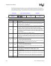
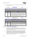
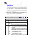
11.7.8 DMA Channel 1 Base Address Register
DMA channel 1 base address register (DBAR1) is a 32-bit register that is used to specify the base
address of the off-chip frame buffer for DMA channel 1. The base address pointer register can be
both read and written. Addresses programmed in the base address register must be aligned on
quadword boundaries; the least significant four bits (DBAR1[3:0]) must always be written with
zeros. The user must initialize the base address register before enabling the LCD, and can also
write a new value to it while the LCD is enabled to allow a new frame buffer to be used for the next
frame. The user can change the state of DBAR1 while the LCD controller is active just after the
base address update (BAU) status bit is set with the LCD’s status register, which generates an
interrupt request. This status bit indicates that the value in the base address pointer has transferred
to the current address pointer register and that it is safe to write a new base address value. DMA
channel 1 is used to transfer frame buffer data from off-chip memory to the LCD’s input FIFO and
the palette RAM for single-panel mode, and for the top half of the screen in dual-panel mode. For
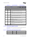
dual-panel operation, the user must perform the following sequence in order: disable the LCD
(LEN=0), program dual panel mode (SDS= 0
→ 1), write the upper panel DMA base address, write
the lower panel DMA base address, enable the LCD
(LEN= 0 → 1). Note that DBAR1 is not reset
and must be initialized before enabling the LCD; question marks indicate that the values are
unknown at reset.