


SA-1110 Developer’s Manual 345
Peripheral Control Module
11.12.1.2 Audio and Telecom Sample Rates and Data Transfer
The UCB1100 and UCB1200 contain both an audio and telecom codec with sample rates that can
be individually programmed, and are derived from the programmed serial clock (SCLK) that is
supplied by the MCP. For the audio codec, the sample rate is derived by dividing the serial clock
first by a fixed value of 32, then by a value from 6 to 127. The same is true for the telecom codec,
except that the programmable divisor ranges from 16 to 127. The codec and the MCP both contain
an audio and a telecom sample rate counter. These counters are used to achieve conversion rate
synchronization between the codec and MCP so that data may be coherently transferred between
the MCP and the codec. For the remainder of this description, references made to the audio codec
also apply to the telecom portion of the codec and MCP.
Before enabling the audio codec, the audio sample rate counters within the codec and MCP must be
programmed with the same divisor value so that they have the same sample rate. The codec’s audio
sample rate divisor is programmed by issuing a control register write transfer, and the MCP’s
divisor is programmed using the CPU by writing to the MCP’s control register. Both the MCP and
the codec’s audio counters are reloaded with the programmed modulus value any time the audio
portion of the codec is enabled (which is also accomplished by performing a control register write
transfer), or whenever the sample rate counters reach zero.
The MCP and the audio codec decrement their counters in lock-step with one another, both starting
on the occurrence of the first SFRM pulse after the audio codec is enabled. Samples/conversions
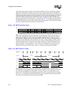
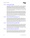
are made each time the audio codec’s counter reaches zero. Figure 11-30 shows the timing of the
audio codec enable and decrements of the MCP and audio codec’s sample counter.
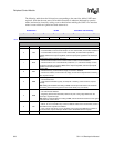
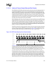
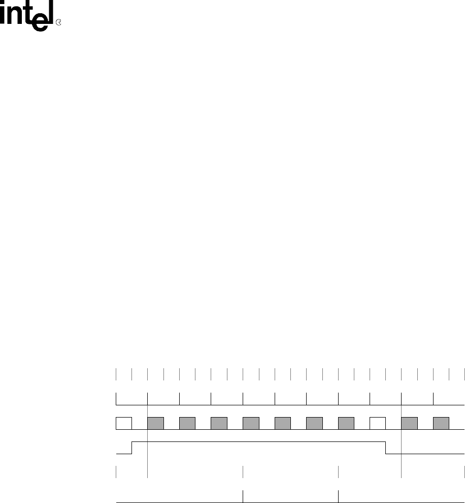
Figure 11-30. MPC/Codec Sampling Counter Synchronization
In Figure 11-30, “Ena,” within the data frame on TXD4, represents a control register write to the codec
to enable the input portion of the audio codec. The register is updated with the write at the end of
subframe and the audio enable signal within the codec goes high. Both the MCP and codec’s audio
sample rate counters then start to decrement on the next SFRM pulse. In the example, a divisor value of
12 is used, causing the counter to decrement to zero after 384 (32*12=384) SCLK cycles occur.
If the input portion of the audio codec is enabled, when the counter reaches zero, a sample and
A-to-D conversion is made and the converted value is placed within the correct field of the codec’s
serial shift register for transmission back to the MCP in the next data frame. If the output portion of
the audio codec is enabled, an audio data value is taken from the received data supplied by the
MCP and is used for a D-to-A conversion. Data used in the D-to-A conversion is always taken
from the previous MCP input frame. If no new data is available within the MCP’s audio transmit
FIFO since the last D-to-A conversion, then the same data is used again (causing audio distortion).
Subframe 0101010101010101010101
SFRM
TXD4
Ena Dis
Audio Ena
Counters 12....12 12.11.10.9.8.7.6.5.4.3.2.1 12.11.10.9.8.7.6.5.4.3.2.1 12.11.10.9.8.7.6 12...................12
Samp/Conv