


SA-1110 Developer’s Manual 309
Peripheral Control Module
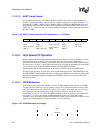
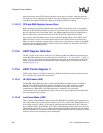
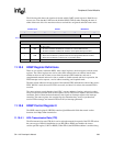
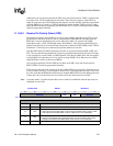
The following table shows the location of the bits within UART control register 4. Both bits are
reset to zero. Note that the UART must be disabled (RXE=TXE=0) when changing the state of
either of these two bits. Also note that writes to reserved bits are ignored and reads return zeros.
11.10.5 HSSP Register Definitions
There are six registers within the HSSP: three control registers, one data register, and two status
registers. The control registers are used to select IrDA transmission rate, address match value,
whether an abort or end of frame occurs when the transmit FIFO underruns, and true or
complemented transmit and receive data; to enable or disable transmit and receive operation, the
FIFO interrupt service requests, receive address matching, and loopback mode.
The data register addresses the top location of the transmit FIFO and bottom location of the receive
FIFO. When it is read, the receive FIFO is accessed, and when it is written, the transmit FIFO is
accessed.
The status registers contain bits that signal CRC, overrun, underrun, framing, and receiver abort
errors as well as the transmit FIFO service request, receive FIFO service request, and end-of-frame
conditions. Each of these hardware-detected events signals an interrupt request to the interrupt
controller. The status registers also contain flags for transmitter busy, receiver synchronized,
receive FIFO not empty, and transmit FIFO not full (no interrupt generated).
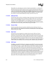
11.10.6 HSSP Control Register 0
The HSSP control register 0 (HSCR0) contains eight different bit fields that control various
functions for 4 Mbps IrDA transmission.
11.10.6.1 IrDA Transmission Rate (ITR)
The IrDA transmission rate (ITR) bit is used to select the transmission speed of the ICP. ITR selects
the correct type of IrDA bit modulation to use (HP-SIR or 4PPM), and enables the correct
serial-to-parallel engine (UART or HSSP). When ITR=0, the HP-SIR modulator is enabled along
0h 8003 0010 UTCR4 Read/Write
7 6 5 4 3 2 1 0
Reserved LPM
HSE
Reset
0 0 0 0 0 0 0 0
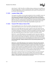
Bits Name Description
0HSE
HP-SIR enable.
0 – HP-SIR modulation disabled; ICP functions as normal UART if ITR=0.
1 – HP-SIR modulation enabled; ICP functions as low-speed IrDA port if ITR=0.
1LPM
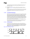
Low-power mode.
0 – Each zero encoded as a pulse that is 3/16 of the programmed bit time if ITR=0.
1 – Each zero encoded as a pulse that is 1.6 µs wide if ITR=0.
7..2 — Reserved.