


304 SA-1110 Developer’s Manual
Peripheral Control Module
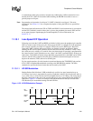
The preamble, start, and stop flags are a mixture of chips that contain either 0, 1, or 2 pulses within
the four time slots. Chips with 0 and 2 pulses are used to construct flags because they represent
invalid data bit pairings (one pulse required per chip to represent one of four bit pairs). The preamble
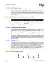
contains 16 repeated transmissions of the four chips: 1000 0000 1010 1000; the start flag contains one
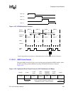
transmission of eight chips: 0000 1100 0000 1100 0110 0000 0110 0000; and the stop flag contains
one transmission of eight chips: 0000 1100 0000 1100 0000 0110 0000 0110. The address, control,
data, and CRC-32 use the standard 4PPM chip encoding to represent 2 bits per chip.
11.10.2.3 Address Field
The 8-bit address field is used by a transmitter to target a select group of receivers when multiple
stations are connected to the same set of serial lines. The address allows up to 255 stations to be
uniquely addressed (00000000 to 11111110). The global address (11111111) is used to broadcast
messages to all stations. Register HSCR1 is used to program a unique address for broadcast
recognition. Control bit HSCR0:AME is used to enable/disable the address match function. Note
that the address of received frames is stored in the receive FIFO along with normal data and that it
is transmitted and received starting with its LSB and ending with its MSB.
11.10.2.4 Control Field
The IPC control field is 8 bits and is optional (as defined by the user). Serial port 2 does not
provide any hardware decode support for the control byte, but instead treats all bytes between the
address and the CRC as data. Note that the control field is transmitted and received starting with its
LSB and ending with its MSB.
11.10.2.5 Data Field
The data field can be any length that is a multiple of 8 bits from 0 to 2045 bytes. The user
determines the data field length according to the application requirements and transmission
characteristics of the target system. Usually a length is selected that maximizes the amount of data
that can be transmitted per frame while allowing the CRC checker to be able to consistently detect
all errors during transmission. Note that serial port 2 does not contain any hardware that restricts
the maximum amount of data transmitted or received. It is up to the user to maintain these limits. If
a data field that is not a multiple of 8 bits is received, an abort is signalled. Also note that each byte
within the data field is transmitted and received starting with its LSB and ending with its MSB.
11.10.2.6 CRC Field
The HSSP uses the established 32-bit cyclic redundancy check (CRC-32) to detect bit errors that
occur during transmission. A 32-bit CRC is computed using the address, control, and data fields,
and is included in each frame. A separate CRC generator is implemented in both the transmit and
receive logic. The transmitter calculates a CRC, and while data is actively transmitted, places the
inverse of the resultant 32-bit value at the end of each frame before the flag is transmitted. In a
similar manner, the receiver also calculates a CRC for each received data frame and compares the
calculated CRC to the expected CRC value contained within the end of each received frame. If the
calculated value does not match the expected value, an interrupt is signalled. The CRC
computation logic is preset to all ones before reception or transmission of each frame and the result
is inverted before it is used for comparison or transmission. Note that unlike the address, control,
and data fields, the 32-bit inverted CRC value is transmitted and received from least significant
byte to most significant, and within each byte the least significant nibble or chip is encoded or
decoded first. The cyclic redundancy checker uses the 32-term polynomial: