


SA-1110 Developer’s Manual 383
Peripheral Control Module
programmed for each of the peripherals’ pins while in sleep mode. When sleep mode is exited, the
user can then reprogram the peripherals and the PPC registers to resume control of the peripherals’
pins. To keep the same pin direction and state after sleep mode has been negated but before the user
reprograms the peripherals, the system control module’s power manager maintains the peripherals’
pin direction and state following sleep negation until the peripheral control hold bit (PSSR:PH),
located in the power manager, is cleared (by writing a one to it). Therefore, the pin direction and
state established during sleep using the sleep mode direction register remains intact following the
negation of sleep until the PH bit is cleared. Once PH is cleared, control of the peripherals’ pins is
given back to the individual peripherals and to the PPC unit.
Most of the SA-1110’s peripherals can take control of one or more GPIO pins (which are normally
controlled within the system control module) to act as input or output triggers, or to drive or supply
clocks to the peripherals. The GPIO unit contains a GPIO alternate function register (GAFR) that
the user must program to give control of the GPIO pins to the individual peripheral units for each
of the alternate functions. The user must also program the GPIO pin direction register (GPDR) for
the corresponding pins that are used by the peripheral units. The GPIO pin alternate functions are
then enabled within the individual peripherals using a control bit. However, two control bits exist
within the PPC that configure six of the GPIO unit’s pins for peripheral alternate functions.
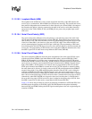
Serial port 1 and serial port 4 both contain two serial-to-parallel engines that operate independently.
However, because each port contains only one set of serial pins, the user can assign these pins to
only one of the two protocols at a time. To allow the user to utilize both protocols, the PPC can
assign one of its two serial-to-parallel engines to the pins that are dedicated to the port, and the
other to a set of GPIO pins. Serial port 1 contains a GPCLK and a UART. By setting a bit in the
PPC and the appropriate GAFR and GPDR bits in the GPIO unit, serial port 1 defaults to the
GPCLK operation, TXD1 and RXD1 pins are given to the PPC, and the UART transmits via the
GPIO 14 pin and receives via the GPIO 15 pin.
When the SA-1110 is reset or enters sleep mode, the GPIO unit’s registers are reset, which gives
control of the GPIO pins back to the system control module.
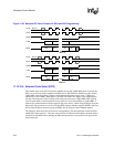
11.13.2 PPC Register Definitions
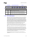
There are five registers within the PPC: one pin direction register, one pin state register, one pin
assignment register, one sleep mode pin direction register, and one pin flag register.
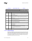
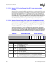
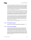
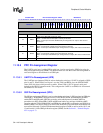
11.13.3 PPC Pin Direction Register
Pin direction is controlled by programming the PPC pin direction register (PPDR). The PPDR
contains individual direction control bits for 22 of the 24 peripheral pins. Serial port 0 has
dedicated pins (UDC+ and UDC-) that are not controlled by the PPC when the UDC is disabled.
Each bit is used only if the corresponding peripheral that it controls is disabled. Provided the
corresponding peripheral is disabled, if the direction bit is programmed to a one, the pin is an
output. If it is programmed to a zero, it is an input. Following reset, all peripherals are disabled,
which causes the PPC to take control of all of their pins. Serial ports 1..3 contain individual enables
for their transmit and receive serial engines. Thus, if only half-duplex transmission is needed, one
pin can be used for serial communication and the other for digital I/O communication. Note that
PPDR is reset such that all the pins are configured as inputs. For reserved bits, writes are ignored
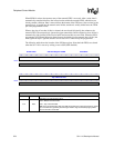
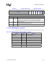
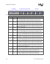
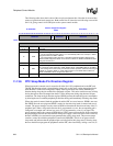
and reads return ones. The following table shows the location of each pin direction bit and to which
peripheral pin it corresponds.