


SA-1110 Developer’s Manual 241
Peripheral Control Module
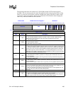
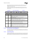
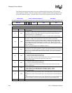
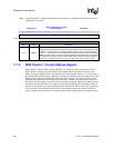
The following table shows the location of the four bit fields located in LCD control register 2
(LCCR2). The LCD controller must be disabled (LEN=0) when changing the state of any field
within this register.
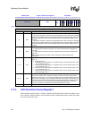
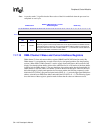
11.7.6 LCD Controller Control Register 3
LCD controller control register 3 (LCCR3) contains seven different bit fields that are used to
control various functions within the LCD controller.
0h B010 0024 LCCR2: LCD Control Register 2 Read/Write
31 30 29 28 27 26 25 24 23 22 21 20 19 18 17 16 15 14 13 12 11 10 9 8 7 6 5 4 3 2 1 0
BFW EFW VSW
LPP
Reset
0 0 0 0 0 0 0 0 0 0 0 0 0 0 0 0 0 0 0 0 0 0 0 0 0 0 0 0 0 0 0 0
Bits Name Description
9..0 LPP
Lines per panel.
Value (from 1 to 1024). Used to specify number of lines per panel. For single-panel mode,
this represents the total number of lines on the LCD display; for dual-panel mode, this
represents half the number of lines on the whole LCD display.
Lines/panel = (LPP+1).
15..10 VSW
Vertical sync pulse width.
In active mode (PAS=1), value (from 0 to 63). Used to specify number of line clock periods
to pulse the L_FCLK pin at the end of each frame after the end-of-frame wait (EFW) period
elapses. Frame clock used as VSYNC signal in active mode.
In passive mode (PAS=0), value (from 0 to 63). Used to specify number of extra line clock
periods to insert after the end-of-frame. Note that the width of L_FCLK is not affected by
VSW in passive mode and that line clock does transition during the insertion of the extra
line clock waitstate periods. Also note that both EFW and BFW should be set to zero in
passive mode.
VSYNC width = (VSW+1).
23..16 EFW
End-of-frame line clock wait count.
In active mode (PAS=1), value (from 0 to 255). Used to specify number of line clock periods
to add to the end of each frame. Note that line clock does transition during the insertion of
the extra line clock periods. EFW should be cleared to zero (disabled) in passive mode.
31..24 BFW
Beginning-of-frame line clock wait count.
In active mode (PAS=1), value (from 0 to 255). Used to specify number of line clock periods
to add to the beginning of a frame before the first set of pixels is output to the display. Note
that line clock does transition during the insertion of the extra line clock periods. BFW
should be cleared to zero (disabled) in passive mode.
Beginning-of-frame wait=0 when BFW=0
Beginning-of-frame wait=(BFW +1) when BFW is non-zero