


SA-1110 Developer’s Manual 413
Boundary-Scan Test Interface 16
The boundary-scan interface conforms to the IEEE Std. 1149.1 – 1990, Standard Test Access Port
and Boundary-Scan Architecture. (Refer to this standard for an explanation of the terms used in
this section and for a description of the TAP controller states.) The Intel
®
StrongARM
*
SA-1110
Microprocessor (SA-1110) supports only JTAG continuity testing.
16.1 Overview
The boundary-scan interface provides a means of driving and sampling all the external pins of the
device irrespective of the core state. This function permits testing of both the device's electrical
connections to the circuit board and (in conjunction with other devices on the circuit board having
a similar interface) testing the integrity of the circuit board connections between devices. The
interface intercepts all external connections within the device, and each such “cell” is then
connected together to form a serial shift register (the boundary-scan register). The whole interface
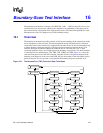
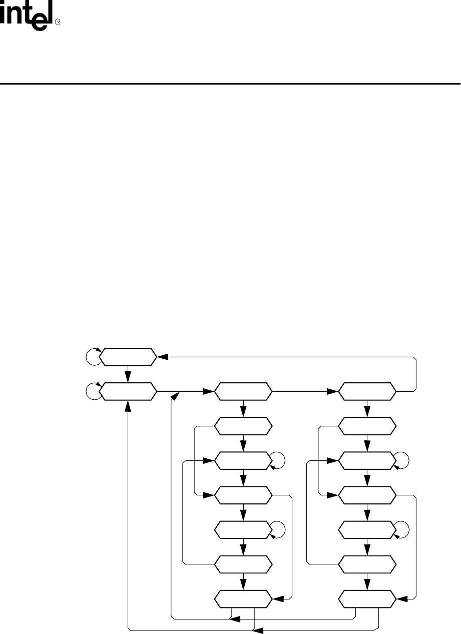
is controlled via five dedicated pins: TDI, TMS, TCK, nTRST, and TDO. Figure 16-1 shows the
state transitions that occur in the TAP controller. Note that all SA-1110 signals participate in the
boundary scan. However, in the case of the PWR_EN pin, the contents of the scan latches are not
placed on the pin. This is to prevent a scan operation from turning off power to the SA-1110.
Figure 16-1. Test Access Port (TAP) Controller State Transitions
Select-IR-Scan
Capture-IR
tms=0
Shift-IR
tms=0
Exit1-IR
tms=1
Pause-IR
tms=0
Exit2-IR
tms=1
Update-IR
tms=1
tms=0
tms=0
tms=1
tms=1
tms=0
Select-DR-Scan
Capture-DR
tms=0
Shift-DR
tms=0
Exit1-DR
tms=1
Pause-DR
tms=0
Exit2-DR
tms=1
Update-DR
tms=1
Test-Logic Reset
Run-Test/Idle
tms=0
tms=1
tms=0
tms=0
tms=0
tms=1
tms=1
tms=0
tms=1 tms=1
tms=1
tms=1 tms=1tms=0 tms=0