SA-1110 Developer’s Manual 87
System Control Module
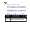
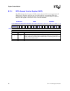
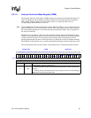
9.2.1.3 Interrupt Controller Mask Register (ICMR)
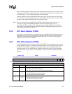
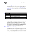
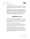
The interrupt controller mask register (ICMR) contains one mask bit per pending interrupt bit (32
total). The mask bits control whether a pending interrupt bit will generate a processor interrupt
(IRQ or FIQ). When a pending interrupt becomes active, it is sent to the CPU only if its
corresponding ICMR mask bit is set to a one.
Note: When the DIM bit in the Interrupt Controller Control Register (ICCR) is set to a 0 the mask bits are
ignored when the SA-1110 is in idle mode. While in idle, if any interrupt source makes a request,
the corresponding pending bit is set and the interrupt automatically becomes active, regardless of
the state of its mask bit.
Mask bits serve two purposes. First, they allow periodic software polling of interruptible sources
while preventing them from actually causing an interrupt. Second, they allow the interrupt handler
routine to prevent interrupts of lower priority from occurring while still maintaining a list of
pending interrupts that may have occurred previously (or during the servicing of another interrupt).
The ICMR is not initialized at reset; a question mark indicates that the values are unknown at reset.
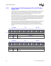
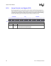
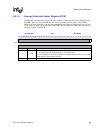
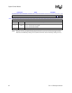
The following table shows the bit locations corresponding to the 32 separate interrupt mask bits.
0h 9005 0004 ICMR Read/Write
31 30 29 28 27 26 25 24 23 22 21 20 19 18 17 16 15 14 13 12 11 10 9 8 7 6 5 4 3 2 1 0
IM31
IM30
IM29
IM28
IM27
IM26
IM25
IM24
IM23
IM22
IM21
IM20
IM19
IM18
IM17
IM16
IM15
IM14
IM13
IM12
IM11
IM10
IM9
IM8
IM7
IM6
IM5
IM4
IM3
IM2
IM1
IM0
Reset ? ? ? ? ? ? ? ? ? ? ? ? ? ? ? ? ? ? ? ? ? ? ? ? ? ? ? ? ? ? ? ?
Bits Name Description
nIMn
Interrupt mask n (where n = 0 through 31).
0 – Pending interrupt is masked from becoming active (interrupts not sent to CPU, Power
Manager).
1 – Pending interrupt is allowed to become active (interrupt sent to CPU, Power Manager).
Note: IM bits are ignored during idle mode.


