264 SA-1110 Developer’s Manual
Peripheral Control Module
11.8.1.4 Field Formats
Individual bits are assembled into groups called fields. Fields are used to construct packets, and
packets are used to construct frames or transactions. The seven USB field types include in this
order:
• Sync
• Packet Identifier
• Address
• Endpoint
• Frame Number
• Data
• CRC
Sync Field
:
A Sync is preceded by the Idle State on the USB bus and is always the first field of any packet. The
first bit of a Sync signals the Start-Of-Packet (SOP) to the SA-1110 UDC or Host. A Sync field is
8-bits wide and consists of seven leading zeros followed by a one (0x80).
Packet Identifier field
:
The Packet Identifier (PID) is 1-byte wide and always follows the Sync field. The first four bits
contain an encoded value that represents packet type (e.g., Token, Data, Handshake, Special), packet
format, and type of error detection. The last four bits contain a check field that ensures the PID is
transmitted without errors. The check field is generated by performing a ones complement of the PID.
The SA-1110 UDC automatically XORs the PID and check field, and than takes the appropriate
action (as prescribed by the USB standard) if the result does not contain all ones, indicating an error
has occurred in transmission.
Address field
:
The Address field contains seven bits and permits 128 unique devices to be placed on the USB.
After the SA-1110 is reset, or a reset is signalled via the USB bus, the SA-1110 UDC (and all of the
other 127 possible devices) is assigned the default address of zero. The Host is then responsible for
assigning unique addresses for each device on the bus. This is performed in the enumeration
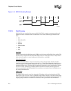
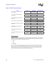
Figure 11-15. NRZI Bit Encoding Example
A4795-01
Bit
Value
Digital
Data
NRZI
Data
11010010


