SA-1110 Developer’s Manual 391
Peripheral Control Module
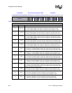
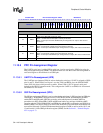
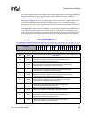
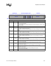
0h 9006 0010 PPC Pin Flag Register: PPFR Read/Write
31 30 29 28 27 26 25 24 23 22 21 20 19 18 17 16 15 14 13 12 11 10 9 8 7 6 5 4 3 2 1 0
Reserved
SP4
SP3 RX
SP3 TX
SP2 RX
SP2 TX
SP1 RX
SP1 TX
Reserved
LCD
Reset 1 1 1 1 1 1 1 1 1 1 1 1 1 1 1 1 1 1 1 1 1 1 1 1 1 1 1 1 1 1 1 1
Bits Name Description
0LCD
LCD controller flag (read-only).
0 – LCD controller enabled.
1 – LCD disabled, PPC currently controlling all 12 of its pins: LDD[7:0], L_PCLK, L_LCLK,
L_FCLK, L_BIAS.
11..1 — Reserved.
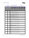
12 SP1 TX
Serial port 1: GPCLK/UART transmit flag (read-only).
0 – GPCLK or UART transmit enabled.
1 – GPCLK and UART transmitters disabled, PPC currently controlling the transmit pin:
TXD1.
13 SP1 RX
Serial port 1: GPCLK/UART receive flag (read-only).
0 – GPCLK or UART receive enabled.
1 – GPCLK and UART receivers disabled, PPC currently controlling the receive pin: RXD1.
14 SP2 TX
Serial port 2: ICP transmit flag (read-only).
0 – HSSP or UART transmit enabled.
1– HSSP and UART transmitters disabled, PPC currently controlling the transmit pin:
TXD2.
15 SP2 RX
Serial port 2: ICP receive flag (read-only).
0 – HSSP or UART receive enabled.
1 – HSSP and UART receivers disabled, PPC currently controlling the receive pin: RXD2.
16 SP3 TX
Serial port 3: UART transmit flag (read-only).
0 – UART transmit enabled.
1 – UART transmit disabled, PPC currently controlling the transmit pin: TXD3.
17 SP3 RX
Serial port 3: UART receive flag (read-only).
0 – UART receive enabled.
1 – UART receive disabled, PPC currently controlling the receive pin: RXD3.
18 SP4
Serial port 4: MCP/SSP flag (read-only).
0 – MCP or SSP enabled.
1– MCP and SSP disabled, PPC currently controlling all 4 of its pins:
TXD4, RXD4, SCLK, SFRM.
31..19 — Reserved.


