


SA-1110 Developer’s Manual 279
Peripheral Control Module
A Control/Status Register is provided for each endpoint: UDC Endpoint 0 Control/Status Register
(UDCCS0), UDC Endpoint 1 Control/Status Register (UDCCS1), and UDC Endpoint 2
Control/Status Register (UDCCS2).
Control Endpoint 0 uses the UDC Endpoint 0 Data Register (UDCD0) to access the 8-entry x
8-byte Control FIFO. When UDCD0 is read, control data received by Endpoint 0 from the Host
exits from the bottom of the Control FIFO; when UDCD0 is written, data that is to be transmitted
from Endpoint 0 to the Host enters the top of the Control FIFO. The UDC Endpoint 0 Write Count
Register (UDCWC) can be used to determine the number of bytes that need to be read from
UDCD0.
Both Endpoint 1 (Bulk OUT) and Endpoint 2 (Bulk IN) share the UDC Data Register (UDCDR) to
access either the 20-entry x 8-byte Receive Data FIFO (Endpoint 1) or the 16-entry x 8-byte
Transmit Data FIFO (Endpoint 2). When the UDCDR is read, data received by Endpoint 1 from the
Host exits from the bottom of the Receive Data FIFO; when the UDCDR is written, data that is to
be transmitted from Endpoint 2 to the Host enters the top of the Transmit Data FIFO.
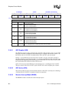
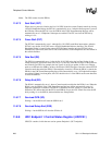
11.8.3 UDC Control Register (UDCCR)
UDCCR contains eight bits: one bit enables/disables the SA-1110 UDC, one bit shows
active/inactive status, and five bits mask the Transmit Data FIFO and Receive Data FIFO service
requests, and one bit is relevant only to the B5 version of the SA-1110. When writing to the
UDCCR, reserved bit-7 should be written as 0.
Note: In order to write to the UDCCR, a USB Host must be connected to the SA-1110.
Note: Due to the internal synchronization required by the SA-1110 UDC’s configuration registers, it is
possible for the CPU to write to the SA-1110 UDC registers and FIFOs too fast. So, a single write
to the SA-1110 UDC must be completed before another write may take place. To ensure that a
single write is completed, it is necessary to observe the effect of the write before another write may
take place. This can be accomplished by writing to a SA-1110 UDC register and then reading back
the same register two times. The second read-back should produce correct data.
0h 8000 0000 UDCCR Read/Write and Read-Only
7 6 5 4 3 2 1 0
Reserved/B
5
SUSIM TIM RIM EIM RESIM UDA
UDD
Reset
0 1 0 0 0 0 0 1
Bits Name Description
0 UDD
UDD disable.
0 – UDD enabled (UDC+ and UDC- used for USB serial transmission/reception).
1 – UDD disabled (SA-1110 UDC is reset).
1 UDA
SA-1110 UDC active (read-only).
0 – SA-1110 UDC currently inactive.
1 – SA-1110 UDC currently active.