


78 SA-1110 Developer’s Manual
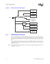
System Control Module
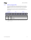
9.1.1.4 GPIO Rising-Edge Detect Register (GRER) and Falling-Edge Detect
Register (GFER)
Each GPIO port can also be programmed to detect a rising-edge, falling-edge, or either transition
on a pin. When an edge is detected that matches the type of edge programmed for the pin, a status
bit is set. The interrupt controller can be programmed to signal an interrupt to the CPU or wake up
the SA-1110 from sleep mode when any one of these status bits is set.
The GPIO rising-edge and falling-edge detect registers (GRER and GFER, respectively) are used
to select the type of transition on a GPIO pin that causes a bit within the GPIO edge detect status
register (GEDR) to be set. For a given GPIO port pin, its corresponding GRER bit is set to cause a
GEDR status bit to be set when the pin transitions from logic level zero (0) to one (1). Likewise,
GFER is used to set the corresponding GEDR status bit when a transition from logic level one (1)
to zero (0) occurs. When the corresponding bits are set in both registers, either a falling- or a
rising-edge transition causes the corresponding GEDR status bit to be set.
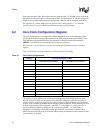
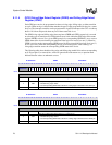
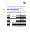
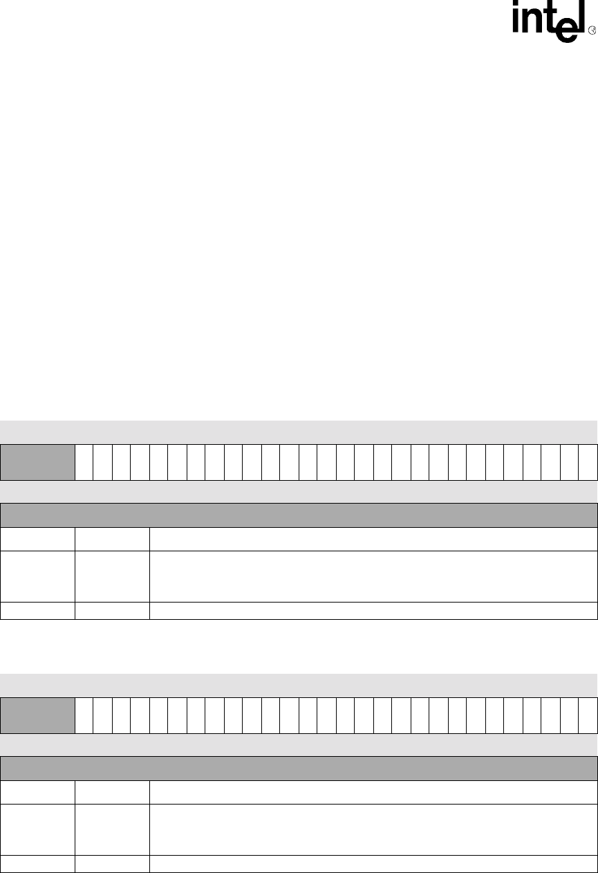
The following table shows both the rising-edge and falling-edge enable bit locations corresponding
to all 28 port pins. For reserved bits, writes are ignored and reads return zero; a question mark
indicates that the values are unknown at reset.
0h 9004 0010 GRER Read/Write
31 30 29 28 27 26 25 24 23 22 21 20 19 18 17 16 15 14 13 12 11 10 9 8 7 6 5 4 3 2 1 0
Reserved
RE27
RE26
RE25
RE24
RE23
RE22
RE21
RE20
RE19
RE18
RE17
RE16
RE15
RE14
RE13
RE12
RE11
RE10
RE9
RE8
RE7
RE6
RE5
RE4
RE3
RE2
RE1
RE0
Reset 0 0 0 0 ? ? ? ? ? ? ? ? ? ? ? ? ? ? ? ? ? ? ? ? ? ? ? ? ? ? 1 1
Bits Name Description
nREn
GPIO pin n rising-edge detect (where n = 0 through 27).
0 – Disable rising-edge detect.
1 – Set corresponding GEDR status bit when a rising edge is detected on the GPIO pin.
31..28 — Reserved
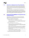
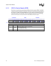
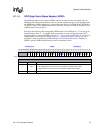
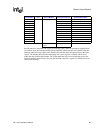
0h 9004 0014 GFER Read/Write
31 30 29 28 27 26 25 24 23 22 21 20 19 18 17 16 15 14 13 12 11 10 9 8 7 6 5 4 3 2 1 0
Reserved
FE27
FE26
FE25
FE24
FE23
FE22
FE21
FE20
FE19
FE18
FE17
FE16
FE15
FE14
FE13
FE12
FE11
FE10
FE9
FE8
FE7
FE6
FE5
FE4
FE3
FE2
FE1
FE0
Reset 0 0 0 0 ? ? ? ? ? ? ? ? ? ? ? ? ? ? ? ? ? ? ? ? ? ? ? ? ? ? 1 1
Bits Name Description
nFEn
GPIO pin n falling-edge detect (where n = 0 through 27).
0 – Disable falling-edge detect.
1 – Set corresponding GEDR status bit when a falling edge is detected on the GPIO pin.
31..28 — Reserved