


SA-1110 Developer’s Manual 243
Peripheral Control Module
decrements each time the ac bias pin is inverted. The number of ac bias pin transitions between
each interrupt request ranges from 0 to 15. Note that programming API=4’h0 disables the ac bias
pin transitions per interrupt function.
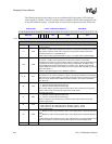
In active mode, L_BIAS is used as an output enable signal. However, signalling of the API interrupt
may still occur. The ACB bit field can be used to count line clock pulses in active mode. When the
programmed number of line clock pulses occurs, an internal signal is transitioned that is used to
decrement the 4-bit counter used by the API interrupt logic. Once this internal signal transitions the
programmed number of times, as specified by API, an interrupt is generated. The user should
program API to zero if the API interrupt function is not required in active mode (PAS = 1).
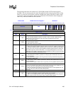
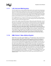
11.7.6.4 Vertical Sync Polarity (VSP)
The vertical sync polarity (VSP) bit is used to select the active and inactive states of the vertical sync
signal in active display mode (PAS = 1), and the frame clock signal in passive display mode. When
VSP=0, the L_FCLK pin is active high and inactive low. When VSP=1, the L_FCLK pin is active
low and inactive high. In active display mode, the L_FCLK pin is forced to its inactive state while
pixels are transmitted during the frame. After the end of the frame and a programmable number of
line clocks periods occur (controlled by EFW), the L_FCLK pin is forced to its active state for a
programmable number of line clocks (controlled by VSW), and is then again forced to its inactive
state. In passive display mode, the L_FCLK pin is forced to its inactive state during the transmission
of the second line of each frame through to the end of the frame. Frame clock is then forced to its
active state on the rising edge of the first pixel clock of each frame. Frame clock remains active
during the transmission of the entire first line of pixels in the frame and is then forced back to its
inactive state on the rising edge of the first pixel clock of the second line of the frame.
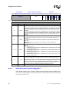
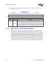
11.7.6.5 Horizontal Sync Polarity (HSP)
The horizontal sync polarity (HSP) bit is used to select the active and inactive states of the
horizontal sync signal in active display mode, and the line clock signal in passive display mode.
When HSP=0, the L_LCLK pin is active high and inactive low. When HSP=1, the L_LCLK pin is
active low and inactive high. Both in active and passive display modes, the L_FCLK pin is forced
to its inactive state whenever pixels are transmitted After the end of each line and a programmable
number of pixel clock periods occur (controlled by ELW), the L_FCLK pin is forced to its active
state for a programmable number of line clocks (controlled by HSW), and is then again forced to its
inactive state.
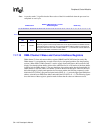
11.7.6.6 Pixel Clock Polarity (PCP)
The pixel clock polarity (PCP) bit is used to select which edge of the pixel clock data is driven out
onto the LCD’s data pins. When PCP=0, data is driven onto the LCD’s data pins on the rising edge
of the L_PCLK pin. When PCP=1, data is driven onto the LCD’s data pins on the falling edge of
the L_PCLK pin.
11.7.6.7 Output Enable Polarity (OEP)
The output enable polarity (OEP) bit is used to select the active and inactive states of the output
enable signal in active display mode. In this mode, the ac bias pin is used as an enable that signals the
off-chip device when data is actively being driven out using the pixel clock. The pixel clock
continuously toggles during operation of active mode (PAS=1). When OEP=0, the L_BIAS pin is
active high and inactive low. When OEP=1, the L_BIAS pin is active low and inactive high. In active
display mode, data is driven onto the LCD’s data pins on the programmed edge of the L_PCLK pin
when L_BIAS is in its active state. Note that OEP does not affect L_BIAS in passive display mode.