


SA-1110 Developer’s Manual 365
Peripheral Control Module
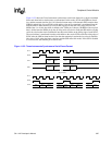
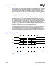
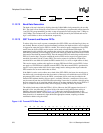
11.12.7 SSP Operation
Following reset, both the MCP and SSP logic within serial port 4 is disabled and control of its pins is
given to the PPC that configures all four pins as inputs. To enable SSP operation, the programmer
should first clear any interruptible status bits, which are set following the reset by writing a one to
them. Next, the user should program the SSP’s control registers with the desired mode of operation,
ensuring that the register containing the SSP enable bit is programmed last. Note that the MCP has
precedence over the SSP and must be disabled first before enabling the SSP. The user can choose to
either “prime” the transmit FIFO by writing up to eight 16-bit values, or allow the transmit FIFO
service request to interrupt the CPU or trigger a DMA transfer to fill the FIFO. Once enabled,
transmission/reception of data begins on the transmit (TXD4) and receive (RXD4) pins, and is
synchronously controlled by the serial clock (SCLK) and serial frame (SFRM) pins.
9ANE
Audio receive FIFO not empty (read-only).
0 – Audio receive FIFO is empty.
1 – Audio receive FIFO is not empty.
10 TNF
Telecom transmit FIFO not full (read-only).
0 – Telecom transmit FIFO is full.
1 – Telecom transmit FIFO is not full.
11 TNE
Telecom receive FIFO not empty (read-only).
0 – Telecom receive FIFO is empty.
1 – Telecom receive FIFO is not empty.
12 CWC
Codec write completed (read-only).
0 – A write to a codec register has not completed since the last time this bit was cleared.
1 – A write to a codec register has been transmitted and has updated the register.
13 CRC
Codec read completed (read-only).
0 – The value read from the addressed codec register has not been returned to MCDR2.
1 – The value read from the addressed codec register is now in MCDR2.
14 ACE
Audio codec enabled (read-only).
0 – The audio codec input and output is disabled (bits 14 and 15 are 0 in Audio Control
Register B).
1 – Audio codec input and/or output is enabled (bits 14 and/or 15 are 1 in Audio Control
Register B).
15 TCE
Telecom codec enabled.
0 – The telecom codec input and output is disabled (bits 14 and 15 are 0 in Telecom
Control Register B).
1 – Telecom codec input and/or output is enabled (bits 14 and/or 15 are 1 in Telecom
Control Register B).
31..16 — Reserved.
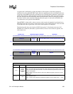
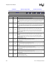
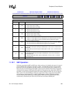
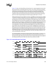
0h 8006 0018 MCP Status Register: MCSR Read/Write and Read-Only
31 30 29 28 27 26 25 24 23 22 21 20 19 18 17 16 15 14 13 12 11 10 9 8 7 6 5 4 3 2 1 0
Reserved
TCE
ACE
CRC
CWC
TNE
TNF
ANE
ANF
TRO
TTU
ARO
ATU
TRS
TTS
ARS
ATS
0 0 0 0 0 0 0 0 0 0 0 0 0 0 0 0 0 0 0 0 0 1 0 1 ? ? ? ? 0 0 0 0
(Sheet 2 of 2)
Bits Name Description