


SA-1110 Developer’s Manual 221
Peripheral Control Module
limits the bandwidth of the LCD’s DMA controller, which, in turn, limits the size and type of screen that
can be controlled. The user must also determine the maximum bandwidth of the SA-1110’s external bus
that the LCD is allowed to use without negatively affecting all other functions that the SA-1110 must
perform. Note that the LCD’s DMA engine has the highest priority on the SA-1110’s internal data bus
structure (ARM system bus) and can “starve” other masters on the bus, including the CPU.
The following sections describe individual functional blocks within the LCD controller, frame buffer and
palette memory organization, and the LCD’s DMA controller. The sections are arranged in order of data
flow, starting with the off-chip frame buffer and ending with the pins that interface to the LCD display.
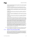
11.7.1.1 DMA to Memory Interface
Palette RAM and encoded pixel data are stored in off-chip memory (usually DRAM) in the frame buffer
and are transferred to the LCD controller’s 5-entry x 32-bit wide input FIFO, on a demand basis, using
the LCD controller’s dedicated DMA controller. The LCD controller is on the ARM system bus (ASB)
rather than the ARM peripheral bus (APB), where all other peripherals are located, because it is a higher
speed synchronous bus that is able to maintain the data rate required for demanding displays, such as
dual-panel color. The LCD’s DMA contains two channels that transfer data from external memory to the
input FIFO. One channel is used for single-panel displays and two are used for dual-panel displays.
The LCD controller issues a service request to the DMA after it has been initialized and enabled.
The DMA automatically performs four word transfers, filling all but one entry of the FIFO. Values
are fetched from the bottom of the FIFO, one entry at a time, and each 32-bit value is unpacked into
individual pixel encodings, of 4, 8, 12, or 16 bits each. After the value is removed from the bottom
of the FIFO, the entry is invalidated and all data in the FIFO is transferred down one entry. When
four of the five entries are empty, a service request is issued to the DMA. If the DMA is not able to
keep the FIFO filled with enough pixel data due to insufficient external memory access speed and
the FIFO is emptied, the FIFO underrun status bit is set and an interrupt request is made.
11.7.1.2 Frame Buffer
The frame buffer is in an off-chip memory area used to supply enough encoded pixel values to fill the
entire screen one or more times. At the start or lowest order address of the LCD controller’s frame buffer
is either a 32- or 512-byte buffer used to store the lookup palette data for each frame. A 32-byte buffer is
used to load the top 16 entries of the palette for 4-, 12-, or 16-bit pixel encodings, and a 512-byte buffer
is used to load the entire 256-entry palette for 8-bit pixel encodings. Note that the LCD’s on-chip palette
is not used for 12- and 16-bit pixel encodings; the PBS field must be programmed to select 12- and
16-bit pixel mode and the remainder of the 32 bytes at the top of the frame buffer must be zero-filled
even though the data is not used.
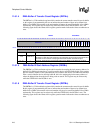
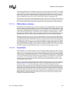
Each time a new frame is fetched from the frame buffer, the LCD controller’s palette is first loaded with
the data contained within the palette buffer. Each of the 16 or 256 palette entries is stored in adjacent
half-words. Figure 11-3 shows the palette-entry organization for little and big endian memory
organization. The user can select how the LCD views the ordering of frame buffer palette/pixel entries
by programming the big/little endian select (BLE) bit in LCD control register 0. In little endian mode,
palette entries are ordered starting with the least significant half-word, followed by the most significant.
In big endian mode, palette entries are ordered starting with the most significant half-word, followed by
the least significant. Note that the ordering of the 4-bit R, G, B, and monochrome pixel data (and the
PBS field) does not change between big and little endian modes; only the relative positioning of the
individual 16-bit palette entries changes.