240 SA-1110 Developer’s Manual
Peripheral Control Module
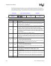
generates a wait period ranging from 0 to 255 line clock cycles (setting EFW=8’h00 disables the
EOF wait count). Note that the line clock pin, L_LCLK, does not transition during the generation
of the EFW line clock periods.
In passive mode, EFW should be set to zero such that no end-of-frame waitstates are generated.
VSW should be used exclusively in passive mode to insert line clock waitstates to allow the LCD’s
DMA to fill the palette and process a number of pixels before the start of the next frame.
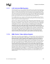
11.7.5.4 Beginning-of-Frame Line Clock Wait Count (BFW)
The 8-bit beginning-of-frame line clock wait count (BFW) field is used in active mode (PAS=1) to
specify the number of line clocks to insert at the beginning of each frame. The BFW count starts
just after the VSYNC signal for the previous frame has been negated. After this has occurred, the
value in BFW is used to count the number of line clock periods to insert before starting to output
pixels in the next frame. BFW generates a wait period of 0, or a range from 2 to 256 extra line
clock cycles (BFW=8’h00 disables the BOF wait count). Note that the line clock pin, L_LCLK,
does transition during the generation of the BFW line clock wait periods.
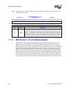
In passive mode, BFW should be set to zero such that no beginning-of-frame waitstates are
generated. VSW should be used exclusively in passive mode to insert line clock waitstates to allow
the LCD’s DMA to fill the palette and process a number of pixels before the start of the next frame.


