


SA-1110 Developer’s Manual 227
Peripheral Control Module
time it is low, while other screens produce more intense colors/grays when the average time the
pixel is low is longer. The user should program the palette appropriately depending on whether a
one on the pixel line turns the pixel on or off. The dither generator also uses the intensity of
adjacent pixels in its calculations to give the screen image a smooth appearance. The proprietary
dither algorithm is optimized to provide a range of intensity values that match the eye’s visual
perception of color/gray gradations. In color mode, three separate dither blocks are used to process
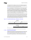
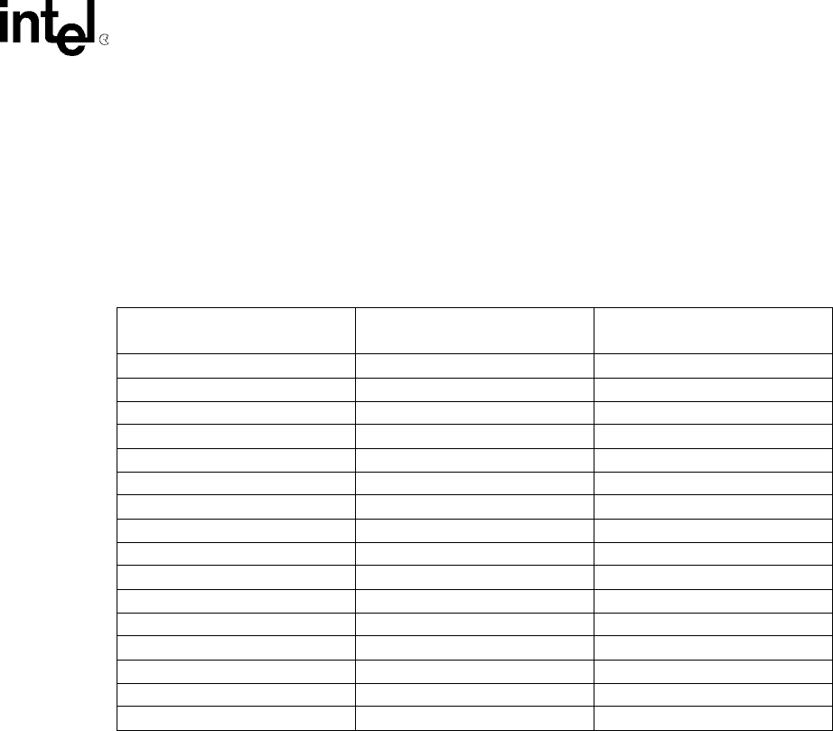
the three color components: red, green, and blue. Table 11-8 summarizes the duty cycle and
resultant intensity level for all 15 color/gray-scale levels.
11.7.1.6 Output FIFO
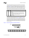
The LCD controller contains a 19-entry x 16-bit wide output FIFO that is used to store pixel pin data
before it is driven out to the pins. Each time a modulated pixel value is output from the dither
generator, it is placed into a serial shifter. The size of the shifter is controlled by programming the
color/monochrome select and single- and dual-panel, double pixel data, and passive/active select bits
in the LCD’s control registers and the pixel bit size within palette entry 0 in the frame buffer. The
shifter can be configured to be 4, 8, or 16 bits wide. Four pins are used for single-panel monochrome
screens; 8 pins are used for single- and dual-panel monochrome screens as well as single-panel color
displays; 12 pins are used for active displays; and 16 pins are used for dual-panel color and active
displays. Once the correct number of pixels have been placed within the shifter (4-, 8-, or 16-pixel
values), the value is transferred to the top of the output FIFO. The value is then transferred down until
it reaches the last empty location within the FIFO. Each time a value is taken from the bottom of the
FIFO, the entry is invalidated and all data in the FIFO moves down one position.
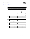
11.7.1.7 LCD Controller Pins
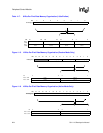
Pixel data is removed from the bottom of the output FIFO and is driven in parallel onto the LCD’s
data lines on the edge selected by the pixel clock polarity (PCP) bit. For a 4-bit wide bus, data is
driven onto the LCD data lines LDD [3:0] starting with the most significant bit. For an 8-bit wide
bus, data is driven onto LDD[7:0]; for a 12-bit bus GPIO[5:2] and LDD[7:0]; and for a 16-bit bus
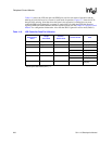
Table 11-8. Color/Gray-Scale Intensities and Modulation Rates
Dither Value
(4-Bit Value from Palette)
Intensity
(0% Is Black)
Modulation Rate
(Ratio of ON to ON+OFF Pixels)
0000 0.0% 0
0001 11.1% 1/9
0010 20.0% 1/5
0011 26.7% 4/15
0100 33.3% 3/9
0101 40.0% 2/5
0110 44.4% 4/9
0111 50.0% 1/2
1000 55.6% 5/9
1001 60.0% 3/5
1010 66.6% 6/9
1011 73.3% 11/15
1100 80.0% 4/5
1101 88.9% 8/9
1110 100.0% 1
1111 100.0% 1