


248 SA-1110 Developer’s Manual
Peripheral Control Module
Note: A question mark (?) signifies that the Reset value of that bit is undefined when the processor has
completed its reset cycle.
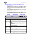
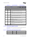
11.7.11 LCD Controller Status Register
The LCD controller status register (LCSR) contains bits that signal overrun and underrun errors for
both the input and output FIFOs, ac bias pin transition count, LCD disabled, DMA base update
ready, and DMA transfer bus error conditions. Each of these hardware-detected events signal an
interrupt request to the interrupt controller.
Each of the LCD’s status bits signal an interrupt request as long as the bit is set. Once the bit is
cleared, the interrupt is cleared. Read/write bits are called status bits (read-only bits are called
flags). Status bits are referred to as “sticky” (once set by hardware, they must be cleared by
software). Writing a 1 to a sticky status bit clears it; writing a zero has no effect. Read-only flags
are set and cleared by hardware; writes have no effect. The user has the ability to mask all LCD
interrupts by clearing bit 12 within the interrupt controller mask register (ICMR). See the
Section 9.2, “Interrupt Controller” on page 9-83.
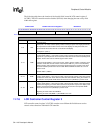
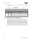
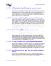
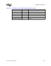
0h B010 0018
DBAR2: DMA Channel 2 Base
Address Register
Read/Write
31 30 29 28 27 26 25 24 23 22 21 20 19 18 17 16 15 14 13 12 11 10 9 8 7 6 5 4 3 2 1 0
DMA Channel 2 Base Address Pointer
Reset
? ? ? ? ? ? ? ? ? ? ? ? ? ? ? ? ? ? ? ? ? ? ? ? ? ? ? ? ? ? ? ?
Bits Name Description
31..0 DBAR2
DMA channel 2 base address pointer.
Used to specify the base physical address of the frame buffer within off-chip memory for
the lower half of the display in dual-panel operation. Value in DBAR2 is transferred to
current address pointer register 2 when LCD is first enabled (LEN= 0 → 1) and when the
current address pointer value reaches the end-of-frame buffer. DBAR2 should be written
only when the LCD is disabled or immediately after an interrupt is generated by setting the
base address update status (BAU) bit. The base address must be on a quadword
boundary. The user must always write bits 0 through 3 to zero.
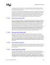
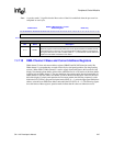
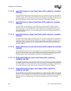
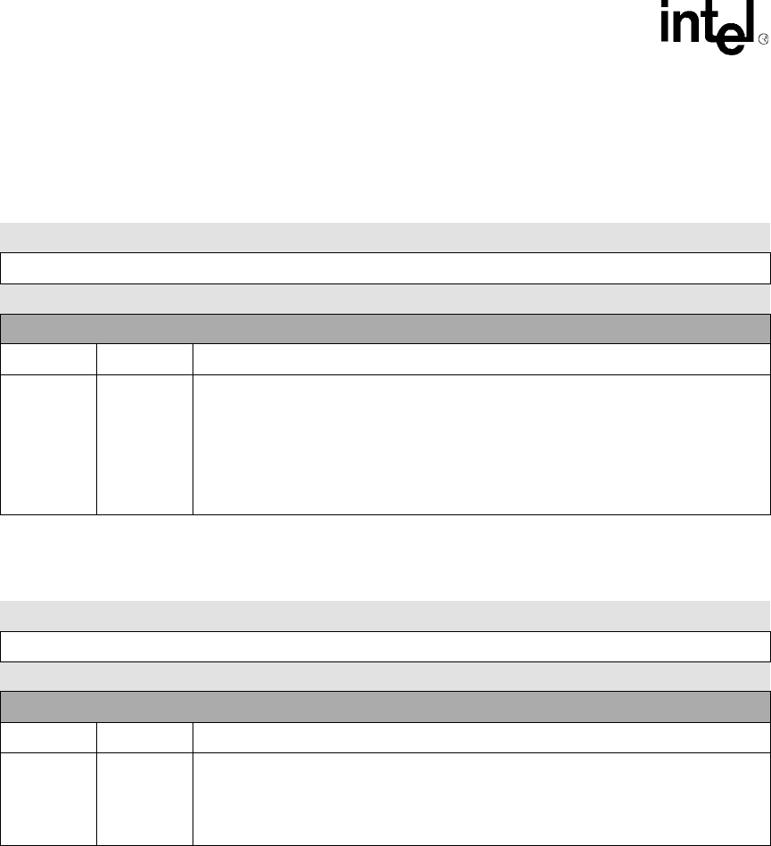
0h B010 001C
DCAR2: DMA Channel 2 Current
Address Register
Read/Write
31 30 29 28 27 26 25 24 23 22 21 20 19 18 17 16 15 14 13 12 11 10 9 8 7 6 5 4 3 2 1 0
DMA Channel 2 Current Address Pointer
Reset
? ? ? ? ? ? ? ? ? ? ? ? ? ? ? ? ? ? ? ? ? ? ? ? ? ? ? ? ? ? ? ?
Bits Name Description
31..0 DCAR2
DMA channel 2 current address pointer.
Read-only register. Continuously reflects the current physical address that DMA channel 2
is transferring from or will use in the next transfer. Base address register is transferred to
this register whenever the LCD is first enabled and when the current address is equal to the
calculated end address of the buffer.