


SA-1110 Developer’s Manual 363
Peripheral Control Module
data from the receive FIFO because DMA service and CPU interrupt requests are made only when
four or more bytes reside within the FIFO (3, 2, or 1 bytes may remain at the end of a frame). This
bit does not request an interrupt.
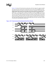
11.12.6.13 Codec Write Completed Flag (CWC) (read-only, noninterruptible)
The codec write completed (CWC) flag is set after the following sequence occurs: a register write
command is issued to the codec by writing to MCDR2; the write command is sent to the codec via
subframe 0; the data value is latched within the addressed codec register at the beginning of
subframe 1 (the 65th bit of the frame); the address and value that was written is returned to the
MCP via the next subframe 0; and the returned values are latched in MCDR2. CWC is
automatically cleared when MCDR2 is read or written. This bit does not request an interrupt.
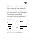
11.12.6.14 Codec Read Completed Flag (CRC) (read-only, noninterruptible)
The codec read completed (CRC) flag is set after the following sequence occurs: a register read
command is issued to the codec by writing to MCDR2; the read command is sent to the codec via
subframe 0; the data value contained within the addressed codec register is loaded into the codec’s
serial shift register during subframe 0 (the 41st bit of the frame); the address and value that was
read is returned to the MCP via the same subframe 0; and the returned values are latched in
MCDR2. CRC is automatically cleared when MCDR2 is read or written. This bit does not request
an interrupt.
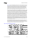
11.12.6.15 Audio Codec Enabled Flag (ACE) (read-only, noninterruptible)
The audio codec enabled (ACE) flag indicates when the audio codec input and/or output is enabled,
which in turn, indicates that the audio sample rate counter is enabled. This flag is set after the
following sequence occurs: a register write command is issued to Audio Control Register B
(register 8), and bit 14 and/or 15 is set (aud_in_ena and/or aud_out_ena) by writing to MCDR2; the
write command is sent to the codec via subframe 0; the data value is latched within codec register
8; and SFRM is asserted to indicate the start of the next frame. ACE is automatically cleared using
the same sequence with the exception that bits 14 and 15 are cleared, disabling both the input and
output paths of the audio codec. This bit does not request an interrupt.
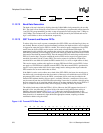
11.12.6.16 Telecom Codec Enabled Flag (TCE) (read-only, noninterruptible)
The telecom codec enabled (TCE) flag indicates when the telecom codec input and/or output is
enabled, which in turn, indicates that the telecom sample rate counter is enabled. This flag is set
after the following sequence occurs: a register write command is issued to Telecom Control
Register B (register 6), and bit 14 and/or 15 is set (tel_in_ena or tel_out_ena) by writing to
MCDR2; the write command is sent to the codec via subframe 0; the data value is latched within
codec register 6; and SFRM is asserted to indicate the start of the next frame. TCE is automatically
cleared using the same sequence with the exception that bits 14 and 15 are cleared, disabling both
the input and output paths of the telecom codec. This bit does not request an interrupt.
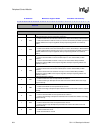
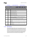
The following table shows the bit locations corresponding to the status and flag bits within the
MCP status register. MCSR contains a collection of read/write, read-only, interruptible, and
noninterruptible bits (refer to the bit descriptions above). Writes to read-only bits have no effect.
The user must clear set status bits by writing ones to them before enabling the MCP. Note that
writes to reserved bits are ignored and reads return zeros; question marks indicate that the values
are unknown at reset.