108 SA-1110 Developer’s Manual
System Control Module
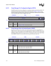
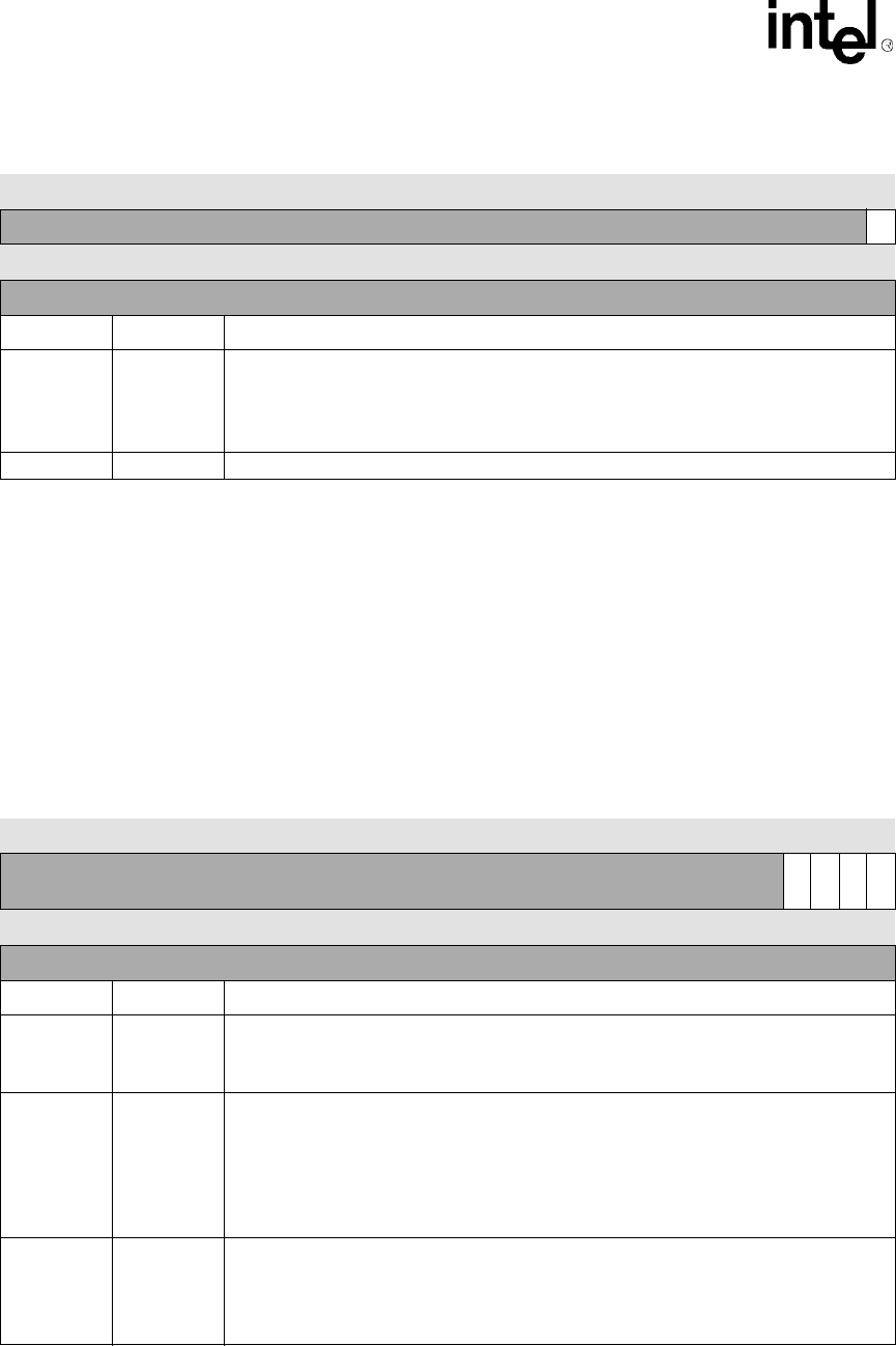
9.5.7.2 Power Manager General Configuration Register (PCFR)
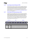
The PCFR contains bits used to configure various functions within the SA-1110. The OPDE bit, if
set, allows the 3.6864-MHz oscillator to be disabled during sleep mode. This bit is cleared on the
assertion of nRESET. The FP and FS bits control the state of the PCMCIA control pins and the
static memory control pins during sleep. The following table shows the bit-field definitions for this
register. The FO bit forces the SA-1110 to assume that the 32-kHz oscillator is stable instead of
waiting for the requisite 2–10 seconds using an internal counter. This function is primarily useful
for "warm" hardware resets where the oscillator is already stable when the processor comes out of
reset.
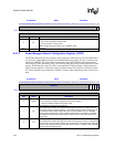
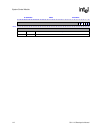
0h 9002 0000 PMCR Read/Write
31 30 29 28 27 26 25 24 23 22 21 20 19 18 17 16 15 14 13 12 11 10 9 8 7 6 5 4 3 2 1 0
Reserved
SF
Reset 0 0 0 0 0 0 0 0 0 0 0 0 0 0 0 0 0 0 0 0 0 0 0 0 0 0 0 0 0 0 0 0
Bits Name Description
0SF
Sleep force.
0 - Do not force invocation of sleep mode.
1 - Force invocation of sleep mode.
Note: This bit is cleared on wake-up or a hardware reset.
31..1 — Reserved
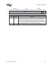
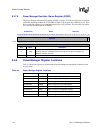
0h 9002 0010 PCFR Read/Write
31 30 29 28 27 26 25 24 23 22 21 20 19 18 17 16 15 14 13 12 11 10 9 8 7 6 5 4 3 2 1 0
Reserved
FO
FS
FP
OPDE
Reset 0 0 0 0 0 0 0 0 0 0 0 0 0 0 0 0 0 0 0 0 0 0 0 0 0 0 0 0 0 0 0 0
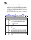
Bits Name Description
0OPDE
3.6864-MHz oscillator power-down enable.
0 – Do not stop the oscillator during sleep mode (reset condition).
1 – Stop the 3.6-MHz oscillator during sleep mode.
1FP
Float PCMCIA controls during sleep mode.
This bit determines whether the PCMCIA control signals are driven to a high (negated)
state during sleep or not driven (floated). A zero indicates that the pins are driven high. A
one indicates that they will be floated. This bit is zero at hardware reset. The PCMCIA
signals affected by this bit are: nPOE, nPWE, nPIOW, nPIOR, and nPCE[2:1]. PSKSEL
and nPREG are derived from address signals and assume the state of the address bus
during sleep.
2FS
Float static chip selects during sleep mode.
This bit determines whether the static chip select control signals are driven to a high during
sleep or floated. A zero indicates that the pins are driven high. A one indicates that they will
be floated. The static chip select signals affected by this bit are: nCS[5:0], nOE, and nWE.
This bit is zero at hardware reset.


