


SA-1110 Developer’s Manual 225
Peripheral Control Module
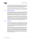
In dual-panel mode, pixels are presented to two halves of the screen at the same time (upper and lower).
A second DMA channel and input FIFO exist to support dual-panel operation. The DMA channels
alternate service requests when filling the two input FIFOs. The palette buffer is implemented in DMA
channel 1, but not channel 2; the base address points to the top of the encoded pixel values for channel 2.
The DMA controller contains a base and current address pointer register. The end address is calculated
automatically by the LCD using the display information such as pixels per line, lines per frame, single-
or dual-panel mode, color or monochrome mode, and bits per pixel, which are programmed by the user.
The base address of both DMA channels must be configured such that the least significant four
address bits are all zero (for example, address bits 3 through 0 must be zero). This requirement
limits the base address of the frame buffer to start at even 4-word (or 16-byte) intervals.
The frame buffer must contain an even multiple of 16 pixels for every line and must be aligned on
a quadword boundary. Many LCD displays are a multiple of 16 pixels wide; however, most
passive LCD displays are not and will ignore extra pixels at the end of each line. Thus for these
types of displays that do not use an even multiple of 16 encoded pixel values, the user must adjust
the start address for each line by adding between 1 and 15 “dummy” pixel values to the end of the
previous line. For example, if the screen that is being driven is 107 pixels wide, and 4-bits/pixel
mode is used, each line is 107 pixels or nibbles in length (53.5 bytes). The next nearest 16-pixel
boundary occurs at 112 pixels or nibbles (56 bytes). Thus, the user must start each new line in the
frame buffer at multiples of 56 bytes by adding an extra 5 “dummy” pixels per line (2.5 bytes). The
user must ensure that the panel being controlled does indeed ignore extra pixel clocks at the end of
each line when a panel with line widths that are non-multiple of 16 pixels are used.
The user must add extra space at the end of the frame buffer. The LCD’s DMA may overshoot the
end of the frame buffer by one burst cycle (4-word read). The LCD’s DMA reads these extra
values, but they are flushed from the input FIFO each time the frame clock is pulsed. The user must
ensure that the four words immediately following the end of the frame buffer reside in legal
memory space (do not cause a bus error if read). Since the LCD does not alter this memory (only
reads are performed), these locations can be used for data storage unrelated to the LCD.
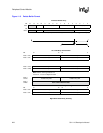
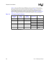
The following equations are used to calculate the total frame buffer size in bytes that is accessed by
the DMA based on varying pixel size encodings and screen sizes. The first term in the equations
represents the size of the palette buffer, the second term is the add-on for the DMA overshoot at the
end of the frame buffer, and the third term is the size required for the encoded pixel values. Note
that for dual-panel mode, the frame buffer size is equally distributed between the two DMA
channels and that DMA channel 2’s buffer is either 32 or 512 bytes smaller (no palette buffer; that
is, the first term in the equations is deleted).
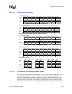
Where n=0 to 15 and is the number of extra “dummy” pixels required per line to make pixels/line
an even multiple of sixteen.
Note: The base address of the frame buffer must start on even 4-word boundaries (the four least
significant address bits [3:0] must be zero).
FrameBufferSize 32 16
Lines
XColumns
2
-----------------------------------------------
èø
æö
2 n
XLines()()++ +=
4 bits/pixel:
FrameBufferSize 512 16 LinesXColumns()nXLines()++ +=
8bits/pixel:
FrameBufferSize 32 16 2 Lines
XColumns()++=
12 or 16 bits/pixel: