


SA-1110 Developer’s Manual 273
Peripheral Control Module
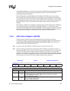
UDCWC-WC bits until the UDCWC-WC bits decrement. Software keeps reading the
UDCWC register until the UDCWC-WC bits indicate a count of 8 bytes.
7. After parsing the data, software sees this is a Control Read command, at which point software
starts loading the UDCD0 Data Register FIFO with the first packet of data and sets the internal
state machine to DATA_STAGE_XMIT. If the command is asking for more data than is
available, only the available data is queued for sending.
8. Software then clears the UDCCS0-OPR bit by writing a 1 to the UDCCS0-SO bit and sets the
UDCCS0-IPR bit, telling the SA-1110 UDC to transmit the data on the next IN. After the bit is
set, the UDCCS0 should be 0000 0010b. If there is no more data to send, then software also
sets the UDCCS0-DE bit by writing a 1 to it. The UDCCS0 register at this time should be 0001
0010b.
9. Return from interrupt.
10. The Host then issues an IN packet, which the SA-1110 UDC will send back to the Host. After
the Host ACKs the SA-1110 UDC, the SA-1110 UDC will clear the UDCCS0-IPR bit and
generate an interrupt.
11. Upon entering the ISR, software will have to examine its internal state machine and see it is in
the state DATA_STAGE_XMIT and needs to transmit more data.
12. The software loads the next 8 bytes of data into the UDCD0 Data Register. Software keeps
reading the UDCWC register until the UDCWC-WC bits indicate the desired bytes have
been written into the data FIFO. The UDCCS0-IPR bit is set and software returns from the
interrupt. The internal state machine is left alone.
13. After the bit is set, the UDCCS0 should be 0000 0010b.
14. Return from interrupt.
15. Go back to step 11 until all of the data is transmitted or the last packet is a short packet.
16. When there no more data left to be transmitted or a short packet, software also sets the
UDCCS0-DE bit by writing a 1 to it. The UDCCS0 register at this time should be 0001 0010b.
17. Software sets the state machine to WAIT_FOR_STATUS.
18. Return from interrupt.
19. When the Host executes the STATUS stage (Zero Length OUT), the SA-1110 UDC sets the
UDDCS0-OPR bit causing an interrupt.
20. Upon entering the ISR, software sees the UDCCS0 register is 0000 0001b, then examines its
internal state machine which is WAIT_FOR_STATUS. When it sees the UDCCS0 has the
OPR bit set, it knows the STATUS stage was sent and will clear the OPR bit and must transfer
its internal state machine back to WAIT_FOR_SETUP.
Case 2: EP0 Control Read with a Premature Status Stage
This happens during every enumeration cycle when the Host does a premature Get Device
Descriptor command.
1. At the beginning of the program, software initializes the internal state machine to
WAIT_FOR_SETUP.
2. Host sends a SETUP command.
3. SA-1110 UDC generates an EP0 Interrupt.
4. The software then determines the UDCCS0-OPR bit is set - 0000 0001b.