SA-1110 Developer’s Manual 177
Memory and PC-Card Control Module
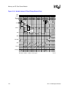
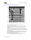
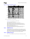
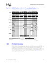
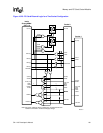
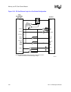
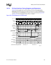
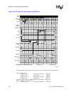
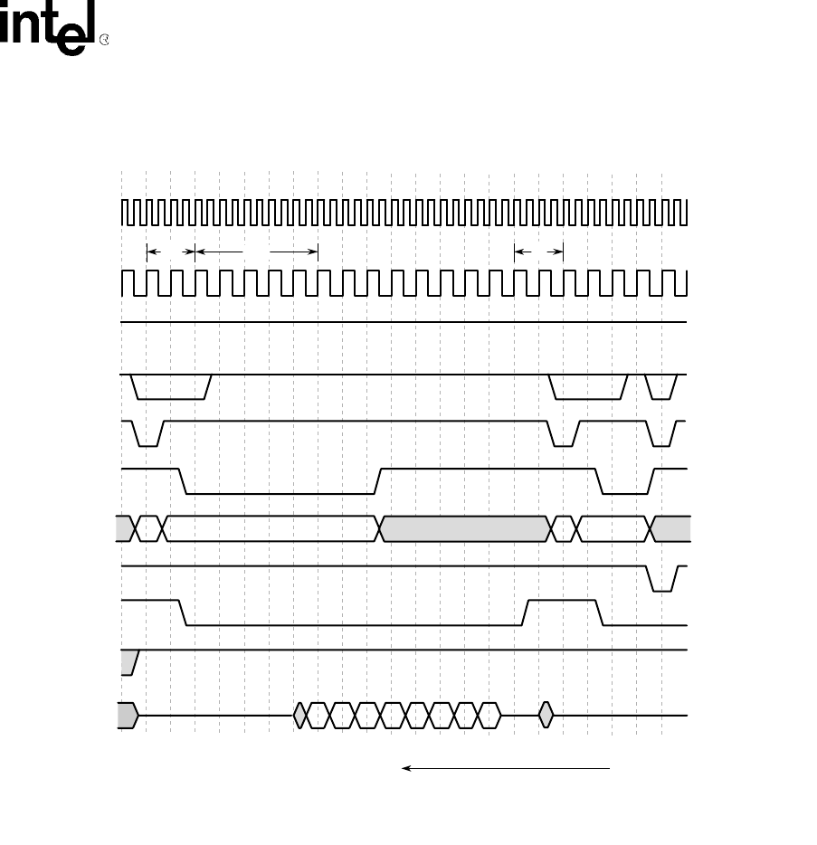
Figure 10-18. SMROM Eight-Beat and Two-Beat Timing for 2 M x 16 Bit Organization
(32 Mbit) at Half-Memory Clock Frequency (MDREFR:K0DB2=1)
10.7 PC-Card Overview
The SA-1110 PC-Card interface provides controls for one PC-Card card slot with a PSKTSEL pin
for support of a second slot. This 16-bit host interface supports 8- and 16-bit peripherals and
handles common memory, I/O, and attribute memory accesses. The interface does not support the
PC-Card DMA protocol. The duration of each access is based on an internally generated clock that
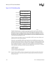
is programmed per address space by fields within the MECR register. Figure 10-19 shows the
memory map for the PC-Card space.
A6644-02
Memory
Clock
SDCLK
SDCKE
command
DRA12-0
nSDRAS
nCS
nSDCAS
nWE
nOE
RD/nWR
ACT READ ACT READ STOP
D
Contents of SMROM/DRAM register fields:
RL=2 cycle SMCNFG:CLO=4 (CL=5 cycle) MDCAS00=0101 0101 0101 0101 0101 0101 0111 1111(binary)
SMCNFG:RA0=4 MDCAS01=0101 0101 0101 0101 0101 0101 0101 0101(binary)
firstlast
time
1234567891011121314151617181920212223
D0 D1 D2 D3 D4 D5 D6 D7
ColRow Row Col
RL 2CL


