


SA-1110 Developer’s Manual 115
System Control Module
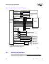
9.6 Reset Controller
The reset controller manages the various reset sources within the SA-1110. From a programmer’s
view, it is visible as two registers: one used to invoke software reset and one to read status after
booting to indicate why the processor was reset.
The four types of reset in the SA-1110 include:
• Hardware reset
Hardware reset is invoked when the nRESET pin is asserted and resets all units in the SA-1110
to a known state. Hardware reset is intended to be used for power-up only. Because the
memory controller receives a full reset, all DRAM contents will be lost during hardware reset.
The RESET_OUT pin is asserted during hardware reset.
• Software reset
Software reset is invoked when the software reset (SWR) bit in the RSRR is set by software.
Software reset applies reset to the majority of the SA-1110 as well as causing the assertion of
the RESET_OUT pin. During software reset, the DRAM refresh and configuration are not
cleared. This allows DRAM contents to survive a software reset. After the SWR bit is set, the
SA-1110 stays reset for 256 processor clocks and then is allowed to boot again.
• Watchdog reset
Watchdog reset is invoked when the watchdog enable bit and the OS timer channel 3 enable bit
are both set (OWER:WME=1 and OIER:E3=1) and the OSMR3 matches the OS timer
counter. When watchdog reset is invoked, the rest of the reset sequence is identical to software
reset. The watchdog enable bit cannot be cleared under program control. Only one of the four
reset types can clear it.
• Sleep reset
Sleep reset is invoked automatically when the SA-1110 enters sleep mode. During sleep mode,
the majority of the processor loses power and will receive reset prior to the negation of the
PWR_EN pin. Sleep reset does not affect the power manager, RTC, or GPIO wake-up register.
During sleep reset, although the memory controller is in reset, the nRAS/nSDCS[3:0] and
nCAS/DQM[3:0] pins are held in the self-refresh state required by the DRAMs.
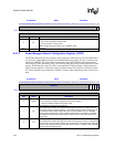
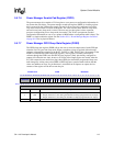
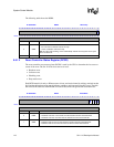
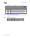
After booting from a reset, software can examine the reset controller reset status register (RCSR) to
determine which types of reset caused the reset condition.
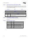
9.6.1 Reset Controller Registers
The reset controller contains two registers, the reset controller software reset register (RSRR) and
the reset controller reset status register (RCSR).
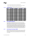
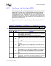
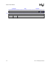
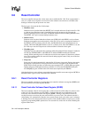
9.6.1.1 Reset Controller Software Reset Register (RSRR)
The reset controller software reset register has a software reset bit, which when set, causes a reset
of the SA-1110. The software reset bit (SWR) is located within the least significant bit of the
write-only reset controller software reset register (RSRR). Writing a one to this bit causes all
on-chip resources to reset but does not cause the PLL to go out of lock. The software reset bit is
self-resetting. It is automatically cleared to zero several system clock cycles after a one is written to
it. Writing zero to the software reset bit has no effect. Care should be taken to restrict access to this
register by programming MMU permissions. For reserved bits, writes have no effect. Reading this
register returns zeros.