


348 SA-1110 Developer’s Manual
Peripheral Control Module
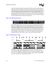
the end of subframe 0 (during the 65th bit of the frame). The control register value and address are
also returned to the MCP and stored in MCP control register 2. The read/write bit is zero in the
return frame. Because the addressed register is updated at the end of subframe 0, the data returned
during the frame in which the write occurred represents the previous contents of the register. The
updated value is returned during the next data frame.
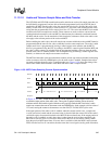
A register read is performed by writing a value to MCP data register 2 that contains the address of
the register and the read/write bit set to a zero. Again, the data is transferred to the serial shifter on
the next rising edge of the SFRM signal and is transmitted to the UCB1100 or UCB1200 during
subframe 0. Because the address and read/write control bit fields occur near the beginning of the
serial stream output, the codec performs the read immediately after the read/write bit is received
(during the 41st bit of the frame) and the value contained within the addressed register is sent back
to the MCP in the same data frame.
Once the codec control register is written with a value to execute a read or write, the operation is
performed every MCP data frame until a new value is written to the register. Thus, continual reads
or writes are made to the addressed codec register until a new read or write operation is configured.
11.12.1.5 External Clock Operation
Under normal operation, the MCP is programmed to use one of two on-chip clocks to produce a
9.585-Mbps or 11.981-Mbps bit rate. This clock is also used to increment the audio and telecom
sample rate counters. The MCP also supports a special mode that allows the user to control the
MCP’s frame rate and audio/telecom sample rates. This mode is useful when sample rates that are
not an integer multiple of 12 MHz are required. In this mode, the MCP uses GPIO 21 to input a
clock supplied from off-chip. The frequency of the off-chip clock can be any value within the
allowable frequency range of the UCB1100, up to 12 MHz. When using GPIO pin 21 for the input
clock, the user must also set bit 21 of the GPIO alternate function register (GAFR) and clear bit 21
of the GPIO pin direction register (GPDR). See the Section 9.1, “General-Purpose I/O” on
page 9-73.
11.12.1.6 Alternate SSP Pin Assignment
MCP operation takes precedence over SSP operation. Thus if both are enabled, serial port 4
defaults to MCP mode. However, if the MCP and SSP both need to be used at the same time,
general-purpose I/O pins 10..13 (GPIO 10..13) can be reassigned by programming the PPC pin
assignment register (PPAR). This allows the MCP dedicated use of the four pins assigned to serial
port 4, and the SSP dedicated use of the GPIO pins. When the SSP pin reassignment (SPR) bit is
set in PPAR, the following pin assignments are made: GPIO 10 is used for transmit, GPIO 11 for
receive, GPIO 12 for serial clock, and GPIO 13 for serial frame. Note that the user must also set
bits 10 through 13 in the GPIO alternate function register (GAFR) as well as set bits 10, 12, and 13,
and clear bit 11 in the GPIO pin direction register (GPDR). Once the reassignment is made, these
pins are no longer usable by the GPIO unit. See the Section 9.1, “General-Purpose I/O” on
page 9-73 for a description of how to program the system control module and the Section 11.13,
“Peripheral Pin Controller (PPC)” on page 11-382 for a description of how to program the PPC
unit.
11.12.1.7 CPU and DMA Register Access Sizes
Bit positioning and addressing of the MCP is described in terms of little endian ordering. All MCP
registers are 32 bits wide. The ARM peripheral bus does not support byte or half-word operations.
All reads and writes of the MCP by the CPU should be word–wide. Four separate dedicated DMA
requests exist for the audio and telecom transmit and receive FIFOs. If the DMA controller is used