SA-1110 Developer’s Manual 85
System Control Module
Several units have more than one source per interrupt signal. When an interrupt is signalled from
one of these units, the interrupt handler routine identifies which interrupt was signalled using the
interrupt controller’s flag register (this identifies the unit that made the request, but not the exact
source). The handler then reads the interrupting unit’s status register to identify which source
within the unit signalled the interrupt. For all interrupts that have one corresponding source, the
interrupt handler routine needs to use only the interrupt controller’s registers to identify the exact
cause of the interrupt.
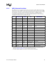
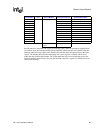
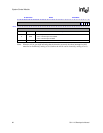
IP 11 System General-purpose I/O 17 “OR” of GPIO edge detects 27-11.
IP10 1 GPIO10edgedetect.
IP 9 1 GPIO 9 edge detect.
IP 8 1 GPIO 8 edge detect.
IP 7 1 GPIO 7 edge detect.
IP 6 1 GPIO 6 edge detect.
IP 5 1 GPIO 5 edge detect.
IP 4 1 GPIO 4 edge detect.
IP 3 1 GPIO 3 edge detect.
IP 2 1 GPIO 2 edge detect.
IP 1 1 GPIO 1 edge detect.
IP 0 1 GPIO 0 edge detect.
Total level 2 interrupt
sources
110
Bit Position Unit Source Module # of Level 2 Sources Bit Field Description


