


382 SA-1110 Developer’s Manual
Peripheral Control Module
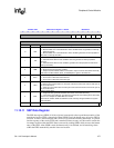
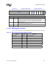
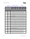
11.12.14 SSP Register Locations
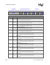
Table 11-21 shows the registers associated with the SSP and the physical addresses used to access them.
11.13 Peripheral Pin Controller (PPC)
The peripheral pin controller (PPC) takes individual control of the LCD’s and serial port 1..4’s pins
when one or more of the units are disabled, allowing the user to utilize them as general-purpose
digital I/O pins to communicate to off-chip resources. When controlled by the PPC, peripheral
control module (PCM) pins operate similarly to GPIO pins except that they cannot perform edge
detection and interrupt generation. The PPC is also used to specify the direction of the peripherals’
pins when sleep mode is entered.
Note that serial ports 1..3 contain individual enables for their transmit and receive serial engines.
Thus, if only half-duplex transmission is needed, one pin can be used for serial communication and
the other for digital I/O communication. Also note that serial port 0’s pins are dedicated to the USB
device controller (UDC), which uses the pins to drive a differential transceiver, preventing them
from being used as digital I/O pins when the UDC is disabled.
11.13.1 PPC Operation
Following a hardware reset of the SA-1110 (nRESET asserted then negated), all peripheral control
module units are disabled, giving control of their pins to the PPC (except serial port 0). The PPC, in
turn, configures all peripheral pins it controls as inputs. Once reset is negated, the user should
program the peripherals as soon as possible, and configure the pins of any peripheral that is not
usable to function as general-purpose I/O signals. This should be done quickly to limit the amount
of power consumed at startup because pins that are intended to function as outputs within the
system are initially configured as inputs, and the receiving device to which they are connected will
float and consume power.
The PPC contains special resources to limit off-chip power consumption during and immediately
following the assertion of sleep mode. The PPC contains a sleep mode direction register, which is
programmed by the user, and individually configures 22 of the peripherals’ pins either as inputs or
outputs during sleep mode. When configured as an output, the pin is forced low in sleep mode. This
special register is required because the first action taken when sleep mode is entered is the assertion
of reset to all the peripherals, which would, in turn, errantly configure all peripheral pins as inputs.
The sleep mode direction register is not reset; the user can maintain the correct direction
Table 11-21. SSP Control, Data, and Status Register Locations
Address Name Description
0h 8007 0060 SSCR0 SSP control register 0
0h 8007 0064 SSCR1 SSP control register 1
0h 8007 0068 — Reserved
0h 8007 006C SSDR SSP data register
0h 8007 0070 — Reserved
0h 8007 0074 SSSR SSP status register
0h 8007 0078 – 0h 8007 FFFF — Reserved