


238 SA-1110 Developer’s Manual
Peripheral Control Module
number of pixel clocks minus one. Note that the pixel clock pin, L_PCLK, does not transition
during these “dummy” pixel clock cycles in passive display mode (pixel clock transitions
continuously in active display mode).
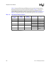
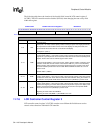
The following table shows the location of the four bit fields located in LCD control register 1
(LCCR1). The LCD controller must be disabled (LEN=0) when changing the state of any field
within this register.
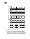
11.7.5 LCD Controller Control Register 2
LCD controller control register 2 (LCCR2) contains four bit fields that are used as modulus values
for a collection of down counters, each of which performs a different function to control the timing
of several of the LCD’s pins.
11.7.5.1 Lines Per Panel (LPP)
The lines per panel (LPP) bit field is used to specify the number of lines or rows present on the LCD
panel being controlled. In single-panel mode, it represents the total number of lines for the entire LCD
display. In dual-panel mode, it represents half the number of lines of the entire LCD display because
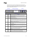
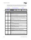
0h B010 0020 LCCR1: LCD Control Register 1 Read/Write
31 30 29 28 27 26 25 24 23 22 21 20 19 18 17 16 15 14 13 12 11 10 9 8 7 6 5 4 3 2 1 0
BLW ELW HSW
PPL
Reset
0 0 0 0 0 0 0 0 0 0 0 0 0 0 0 0 0 0 0 0 0 0 0 0 0 0 0 0 0 0 0 0
Bits Name Description
9..0 PPL
Pixels per line.
Value (from 1 to 1024). Used to specify number of pixels contained within each line on the
LCD display. Pixels/line = (PPL+16).
Note that PPL[3:0] are not implemented but return zeros when read.
15..10 HSW
Horizontal sync pulse width.
Value (from 0 to 63). Used to specify number of pixel clock periods to pulse the line clock at
the end of each line. HSYNC pulse width = (HSW+2).
Note that pixel clock is held in its inactive state during the generation of the line clock in
passive display mode and is permitted to transition in active display mode.
23..16 ELW
End-of-line pixel clock wait count.
Value (from 1 to 255). Used to specify number of pixel clock periods to add to the end of a
line transmission before line clock is asserted. EOL = (ELW+1).
Note that pixel clock is held in its inactive state during the end-of-line wait period in passive
display mode and is permitted to transition in active display mode.
31..24 BLW
Beginning-of-line pixel clock wait count.
Value (from 1 to 255). Used to specify number of pixel clock periods to add to the beginning
of a line transmission before the first set of pixels is output to the display. BOL wait =
(BLW+1).
Note that pixel clock is held in its inactive state during the beginning-of-line wait period in
passive display mode and is permitted to transition in active display mode.