


206 SA-1110 Developer’s Manual
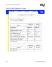
Peripheral Control Module
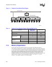
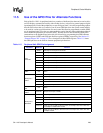
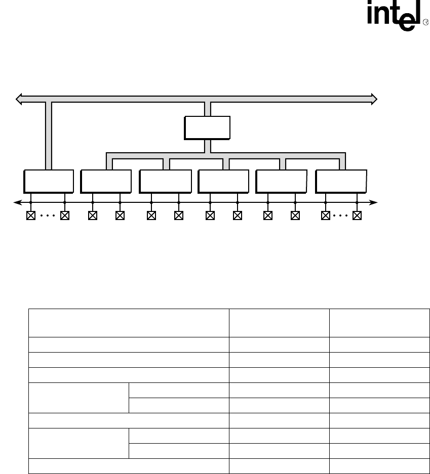
Figure 11-1. Peripheral Control Module Block Diagram
11.2 Memory Organization
Several of the serial ports contain more than one serial engine. Each individual engine is
self-contained (no shared logic or registers) and implements a separate serial protocol. Serial ports
1, 2, and 4 each contain two separate serial engines, totalling eight separate serial engines within all
five serial ports. Each of the eight serial engines, including the peripheral pin controller (PPC), has
been allocated a separate 64 Kbyte block on-chip memory space in which its registers reside.
Although the register width of individual units varies, each register is right justified on word
boundaries. All register accesses via the CPU must be performed using word reads and writes. This
chapter includes a summary of individual peripheral registers. See Appendix A, “Register
Summary,” for a complete summary of all on-chip registers.
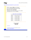
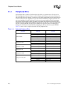
Table 11-1. Peripheral Control Modules’ Register Width and DMA Port Size
Peripheral
Register Width /
DMA Port Size
DMA Burst Size
LCD controller 32 4 words
Serial port 0: UDC 8 8 bytes
Serial port 1: UART 8 4 bytes
Serial port 2: ICP
UART 8 4 bytes
HSSP 8 8 bytes
Serial port 3: UART 8 4 bytes
Serial port 4:
MCP 16 8 bytes
SSP 16 8 bytes
Peripheral pin controller (PPC) 32 N/A
A6833-01
ARM
*
System Bus
ARM Peripheral Bus
L_PCLK
LCD
Controller
L_BIAS UDC+
Serial Port 0
UDC
UDC- TXD1
Serial Port 1
GPCLK/UART
RXD1 TXD2
Serial Port 2
ICP
RXD2 TXD3
Serial Port 3
UART
RXD3 TXD4
Serial Port 4
MCP/SSP
SCLK
DMA
Controller