


242 SA-1110 Developer’s Manual
Peripheral Control Module
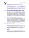
11.7.6.1 Pixel Clock Divider (PCD)
The 8-bit pixel clock divider (PCD) field is used to select the frequency of the pixel clock. PCD can
be any value from 1 to 255 (0 is illegal) and is used to generate a range of pixel clock frequencies
from CCLK/6 to CCLK/514 (where CCLK is the programmed frequency of the CPU clock). The
pixel clock frequency should be adjusted to meet the required screen refresh rate. The refresh rate
depends on: the number of pixels for the target display; whether single- or dual-panel mode is
selected; whether monochrome or color mode is selected; the number of pixel clock waitstates
programmed at the beginning and end of each line; the number of line clocks inserted at the
beginning and end of each frame; the width of the VSYNC signal in active mode or VSW line
clocks inserted in passive mode; and the width of the frame clock or HSYNC signal. All of these
factors alter the time duration from one frame transmission to the next. Different display
manufacturers require different frame refresh rates depending on the physical characteristics of the
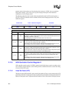
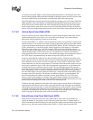
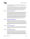
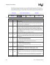
display. PCD is used to alter the pixel clock frequency to meet these requirements. The frequency
of the pixel clock for a set PCD value or the required PCD value to yield a target pixel clock
frequency can be calculated using the two following equations. Note that programming PCD =
8’h00 is illegal.:
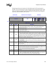
11.7.6.2 AC Bias Pin Frequency (ACB)
The 8-bit ac bias frequency (ACB) field is used to specify the number of line clock periods to count
between each toggle of the ac bias pin (L_BIAS). In passive mode, after the LCD controller is
enabled, the value in ACB is loaded to an 8-bit down counter and the counter begins to decrement
using the line clock. When the counter reaches zero, it stops, the state of L_BIAS is reversed, and the
whole procedure starts again. The number of line clocks between each ac bias pin transition ranges
from 1 to 256. The user should program ACB with the desired number of line clocks minus one.
This pin is used by the LCD display to periodically reverse the polarity of the power supplied to the
screen to eliminate DC offset. If the LCD display being controlled has its own internal means of
switching its power supply, ACB should be set to its maximum value to reduce power consumption
(8’hFF). Note that the ACB bit field has no effect on L_BIAS in active mode. Because the pixel
clock transitions continuously in active mode, the ac bias pin is used as an output enable signal. It
is asserted automatically by the LCD controller in active mode whenever pixel data is driven out to
the data pins to signal the display when it may latch pixels using the pixel clock.
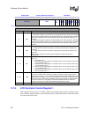
11.7.6.3 AC Bias Pin Transitions Per Interrupt (API)
The 4-bit ac bias pin transitions per interrupt (API) field is used to specify the number of L_BIAS
pin transitions to count before setting the ac bias count status (ACS) bit in the LCD controller
status register that signals an interrupt request. After the LCD controller is enabled, the value in
API is loaded to a 4-bit down counter and the counter decrements each time the ac bias pin is
inverted. When the counter reaches zero, it stops and the ac bias count (ABC) bit is set in the status
register. Once ABC is set, the 4-bit down counter is reloaded with the value in API, and is disabled
until ABC is cleared. When ABC is cleared by the CPU, the down counter is enabled and again
PixelClock
CCLK
2 PCD 2+()
------------------------------
=
PCD
CCLK
2 PixelClock()
-------------------------------------
2–=