


SA-1110 Developer’s Manual 271
Peripheral Control Module
After the Host completes a SET_CONFIGURATION or SET_INTERFACE command, SA-1110
software must decode the command to empty the OUT Endpoint FIFO and allow SA-1110
software to set up the proper power/peripheral configurations.
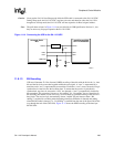
11.8.1.8 Using DMA
A different DMA transfer must be specified for each USB packet, e.g., do not program a 8K DMA
transfer to try to move 128 64-byte USB packets. Also, the USB interrupt must be kept active to
cause a reload of the DMA channel after EACH and EVERY packet is sent or received.
Errors in DMA-based USB transfers can be system dependent. For packet sizes greater than
12-bytes, best results are obtained by specifying modulo-4 packet sizes, e.g., 16-bytes, 64-bytes,
256-bytes. Also, best results are obtained by using an SA1110Bx at 192 MHz or 206 MHz.
11.8.1.9 Software Control of the SA-1110 UDC
11.8.1.9.1 Overview
When an interrupt occurs and the Interrupt Service Routine (ISR) is entered, read the Interrupt
Controller Registers ICPR and ICIP or ICFP to determine which interrupts occurred. If bit 13 of
these registers is set to 1, indicating a SA-1110 UDC service request, read the UDC Status/Interrupt
Register (UDCSR) to determine which SA-1110 UDC interrupt caused the request. Based on
which interrupt caused the request, do the following:
1. Wake-up or GPIOn Interrupt:
a. After wake-up or a GPIOn interrupt, software should read the GPIOn pin.
b. If GPIOn = 0, then the USB cable is not connected and wake-up was due to some other
occurrence.
c. If GPIOn = 1, then the USB cable is connected. Initialize the SA-1110 UDC and clear the
SUSIM bit (bit 6) of UDCCR.
Note: If GPIOn is shared with some other device which can assert an interrupt for wake-up, the USB
cable might need to be disconnected and then reconnected to synchronize to the PC.
2. Reset Interrupt:
a. Software should write a 1 to the RSTIR bit of the UDCSR to clear the reset interrupt.
b. If GPIOn = 0, the USB cable has been disconnected, and the SA-1110 can be put into
sleep mode.
c. If GPIOn = 1, then software should attempt to write a 0 to the SUSIM bit (bit 6) of
UDCCR to unmask the suspend interrupt.
1. If software is able to clear the SUSIM bit, the interrupt was due to reset being negated.
Software should then be able to initialize any required variables and registers.
2. If software is unable to clear the SUSIM bit, the interrupt was due to USB Reset being
asserted by the Host. Return to main.
3. Suspend Interrupt:
a. Software should be able to write a 1 to the SUSIM bit (bit 6) of UDCCR to mask any
further suspend interrupts.
b. Software should be able to write a 1 to the SUSIR bit (bit 3) of UDCSR to clear the
suspend interrupt.