


SA-1110 Developer’s Manual 233
Peripheral Control Module
in subsequent bit-field sections for both passive and active mode. Additionally, the LCD controller
can be configured in active color display mode and used with an external DAC and optionally an
external palette to drive a video monitor. Note that only monitors that implement the RGB data format
can be used; the LCD controller does not support the NTSC standard.
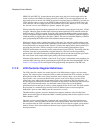
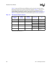
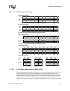
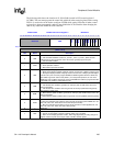
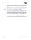
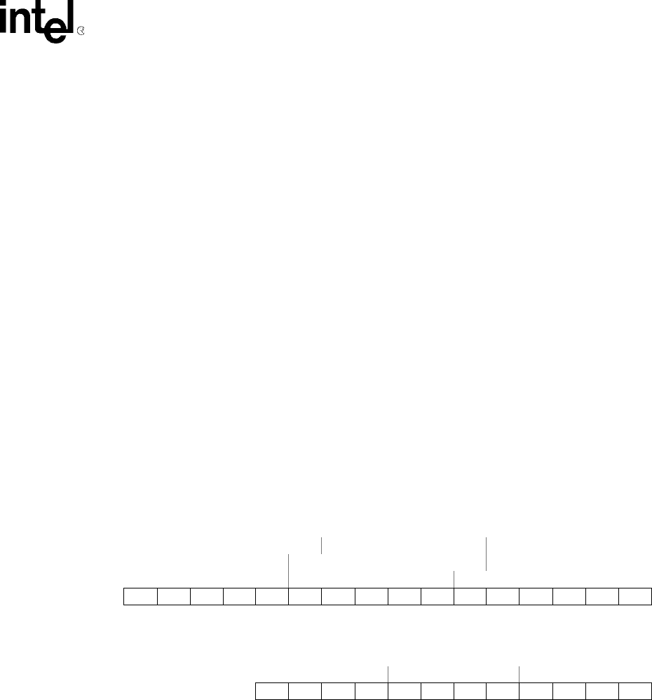
Figure 11-8 shows which bits within each frame buffer entry (for 16-bit/pixel mode) and which bits
within a selected palette entry (for 4- and 8-bit/pixel mode) are sent to the individual LCD data
pins. In active mode, GPIO pins 2..9 are also used. Note that the user must configure GPIO pins
2..5 as outputs (for 4- and 8-bit/pixel mode), and GPIO pins 2..9 as outputs (for 16-bit/pixel mode)
by setting the appropriate bits within the GPIO pin direction register (GPDR) and GPIO alternate
function register (GAFR). See the General-Purpose I/O section for configuration information.
When in 4- or 8-bits/pixel mode, the user should clear GAFR[6:9] to disable the LCD alternate
function and, thereby, prevent unpredictable data from being driven onto GPIO[6:9]. In general, the
user may clear any number of GAFR bits 2..9, to allow the GPIO unit to assume control of unused
GPIO pins for normal digital I/O depending on the required number of data pins.
If the panel that is being controlled contains more data pin inputs than 16, the user may still use the
SA-1110’s LCD controller, but the panel will be limited to a total of 64 K colors. If the user wishes
to maintain the panel’s full range of colors and increase the granularity of the spectrum, the LCD’s
16 data pins should be interfaced to the panel’s most significant R, G, and B pixel data input pins
and the least significant R, G, and B data pins should be tied either high or low. If instead, the user
wishes to maintain the granularity of the spectrum and limit the overall range of colors possible, the
LCD’s 16 data pins should be interfaced to the panel’s least significant R, G, and B pixel data input
pins and the most significant data pins should again be tied either high or low.
Figure 11-8. Frame Buffer/Palette Bits Output to LCD Data Pins in Active Mode
1
However, if GAFR bit 6..9 are cleared within the system control module, these pins can be used as normal GPIO pins.
11.7.3.8 Big/Little Endian Select (BLE)
The big/little endian select (BLE) bit selects whether the LCD controller views external memory
organization of the frame buffer as big or little endian. When BLE=0, little endian mode is selected
and pixel data is organized within the off-chip frame buffer as shown in Figure 11-4 through
Figure 11-6. Pixels are packed into words starting with the least-significant nibble, byte, or
half-word. When BLE=1, big endian mode is selected and pixel data is organized in memory
starting with the most significant nibble, byte, or half-word. When BLE=1, palette entries are
16-Bit/Pixel Mode
Frame Buffer Entry
R5 R4 R R2 R R G4 G3 G2 G1 G0 B4 B3 B2 B1 B0
R4R3 R R1R0G5G4G3G2G1G0B4B3B2B1B0
R4 R3 R2 R1 R0 G4 G3 G2 G1 G0 B5 B4 B3 B2 B1 B0
Bit1514131211109876543210
Data
Pin
GPIO
9
GPIO
8
GPIO
7
GPIO
6
GPIO
5
GPIO
4
GPIO
3
GPIO
2
LDD
7
LDD
6
LDD
5
LDD
4
LDD
3
LDD
2
LDD
1
LDD
0
4- or 8-Bit/PixelMode
Selected Palette Entry
R3 R2 R1 R0 G3 G2 G1 G0 B3 B B B0
Bit 11109876543210
Data
Pin
GPIO
9
GPIO
8
GPIO
7
GPIO
6
GPIO
5
GPIO
4
GPIO
3
GPIO
2
LDD
7
LDD
6
LDD
5
LDD
4
LDD
3
LDD
2
LDD
1
LDD
0