


SA-1110 Developer’s Manual 205
Peripheral Control Module 11
This chapter describes the peripheral control units that are integrated within the Intel
®
StrongARM
*
SA-1110 Microprocessor (SA-1110) and the DMA controller that services them. The
peripheral units include one parallel data port to drive an LCD display, one synchronous serial port,
and four asynchronous serial ports that implement different serial protocol standards. Each section
includes a description of the unit’s operation and the control, data, and status registers used to
configure the unit. The DMA controller acts as the gateway to the peripheral units. It provides
DMA access to these units and control and address decode for programmed I/O accesses between
the processor and registers inside the units. Note that the LCD controller contains its own high
bandwidth DMA controller that is connected to the ARM
*
system bus and is used to read pixel and
palette information from the off-chip frame buffer.
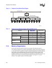
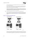
11.1 Read/Write Interface
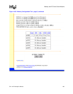
The ARM system bus, shown in Figure 11-1, is a high-performance synchronous bus that connects
the peripheral control module to the SA-1110 CPU and to the external memory controller. The
DMA connects the ARM system bus to the ARM peripheral bus. The ARM peripheral bus
implements a standard asynchronous protocol that is used by all peripherals designed for ARM
chips. This standard allows a single library of peripherals to be developed for the entire ARM
family of CPUs, providing a means to quickly spin off new chip implementations that contain
different peripheral mixes for target applications. Note that the LCD controller interfaces to the
ARM system bus because its throughput requirement is much higher than that of any other serial
peripheral. Placing the LCD on the ARM system bus allows faster synchronous transfers to be
made between the external frame buffer and the LCD controller. Additionally, the LCD controller
contains its own dual-channel DMA controller to supply frame buffer data to the unit.
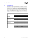
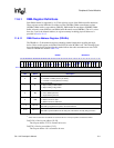
Although the ARM peripheral bus supports 32 bits of data, the register size (width) implemented
for each peripheral is equal to the maximum data size that must be coherently read or written by the
CPU and DMA. This minimizes the size of the peripheral while providing the necessary memory
throughput for the unit. Although the peripherals’ register sizes vary, the ARM peripheral bus does
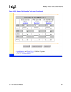
not support byte or half-word accesses. Only word accesses are allowed. Table 11-1 shows the
register width, DMA port size, and DMA burst size of each of the six peripherals (and the PPC)
implemented on the SA-1110.