


SA-1110 Developer’s Manual 209
Peripheral Control Module
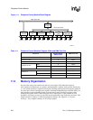
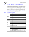
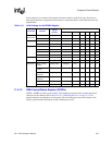
11.5 Use of the GPIO Pins for Alternate Functions
Each of the SA-1110’s six peripheral units has a number of dedicated pins that can be used to drive
an LCD display, communicate serially with off-chip devices, or be used as general-purpose digital
input/output pins. Each of the peripherals, except serial port 0 and 2, also has programming options
that allow the unit to take over control of one or more GPIO pins from the system control module
to be used for various special functions. Several control bits must be programmed to enable GPIO
use by peripheral units. First, the user must enable the special function either within the peripheral
unit or within the peripheral pin controller (PPC). Second, the user must enable the GPIO pin to
communicate to the peripheral and select the pin’s direction by programming the GPIO alternate
function register (GAFR) and GPIO pin direction register (GPDR), respectively. See Section 9.1,
“General-Purpose I/O” on page 9-73 for a description of these GPIO registers. Table 11-5 shows
the GPIO pins that can be used for alternate peripheral pin functions.
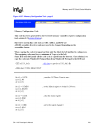
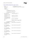
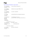
Table 11-5. Peripheral Unit GPIO Pin Assignment
Peripheral GPIO Pin Function
LCD
Controller
GPIO 2 LDD 8 pin for dual-panel color mode.
GPIO 3 LDD 9 pin for dual-panel color mode.
GPIO 4 LDD 10 pin for dual-panel color mode.
GPIO 5 LDD 11 pin for dual-panel color mode.
GPIO 6 LDD 12 pin for dual-panel color mode.
GPIO 7 LDD 13 pin for dual-panel color mode.
GPIO 8 LDD 14 pin for dual-panel color mode.
GPIO 9 LDD 15 pin for dual-panel color mode.
Serial port 0:
USB
N/A None.
Serial port 1:
UART
GPIO 14 Transmit pin for UART when GPCLK and UART are both needed.
GPIO 15 Receive pin for UART when GPCLK and UART are both needed.
GPIO 16 Clock output for GPCLK.
GPIO 17 Reserved
GPIO 18 Sample clock input to UART.
Serial port 2:
ICP
N/A None.
Serial port 3:
UART
GPIO 20 Sample clock input to UART.
Serial port 4:
MPC/SSP
GPIO 10 Transmit pin for SSP when MCP and SSP both needed.
GPIO 11 Receive pin for SSP when MCP and SSP both needed.
GPIO 12 Serial clock pin for SSP when MCP and SSP both needed.
GPIO 13 Serial frame clock pin for SSP when MCP and SSP both needed.
GPIO 19
Clock input pin for SSP to drive the frame and sample rates when other than
nonmultiple of 3.6864 MHz needed.
GPIO 21
Clock input pin for MCP to drive the frame and sample rates when other than
12 Mbps needed.