SA-1110 Developer’s Manual 23
Introduction
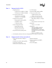
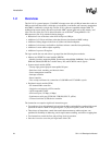
Table 1-3. Feature Additions to the SA-1110 from the SA-110
• Memory controller supporting ROM,
synchronous mask ROM (SMROM),
Flash, DRAM, synchronous DRAM
(SDRAM), SRAM, and SRAM-like
variable latency I/O
• LCD controller
— 1-, 2-, or 4-bit gray-scale levels
— 8-, 12-, or 16-bit color levels
• 230-Kbps UART
• Touch-screen, audio, telecom port
• Infrared data (IrDA) serial port
— 115 Kbps, 4 Mbps
• Six-channel DMA controller
• Integrated two-slot PCMCIA controller
• Twenty-eight general-purpose I/O ports
• Real-time clock with interrupt capability
• On-chip oscillators for clock sources
• Interrupt controller
• Power-management features
— Normal (full-on) mode
— Idle (power-down) mode
— Sleep (power-down) mode
• Four general-purpose interruptible timers
• 12-Mbps USB device controller
• Synchronous serial port (UCB1100,
UCB1200, SPI, TI, Wire)
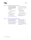
Table 1-4. Feature Additions to the SA-1110 from the SA-1100
• Synchronous DRAM (SDRAM) support
• Synchronous mask ROM (SMROM)
support (32-bit only) on CS0-3
• Ready input signal for variable latency I/O
devices (for example, graphics chips)
• CS4 and CS5 for variable latency I/O
devices, ROM, or Flash memory
• CS3 support for variable latency I/O
devices (instead of SRAM)
• Support for burst (page-mode) read
timings from Flash memory
• Support for 16-bit data busses on all
memory types (except SMROM)
• Support for SRAM, DRAM, and SDRAM
in the same system


