


SA-1110 Developer’s Manual 219
Peripheral Control Module
11.7 LCD Controller
The SA-1110’s LCD controller has three types of displays:
Passive Color Mode Supports a total of 3375 possible colors, displaying any of 256 colors for each
frame.
Active Color Mode Supports up to 65536 colors (16-bit).
Passive Monochrome ModeSupports 15 gray-scale levels.
Display sizes up to 1024 x 1024 pixels are supported. However, the size of encoded pixel data within
the frame buffer limits the maximum size screen the LCD can drive due to memory bus bandwidth.
The LCD controller also supports single- or dual-panel displays. Encoded pixel data is stored in
external memory in a frame buffer in 4-, 8-, 12-, or 16-bit increments and is loaded into a 5-entry
FIFO (32 bits per entry) on a demand basis using the LCD’s own dedicated dual-channel DMA
controller. One channel is used for single-panel displays and two are used for dual-panel displays.
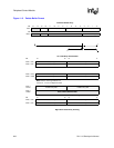
Frame buffer data contains encoded pixel values that are used by the LCD controller as pointers to
index into a 256-entry x 12-bit wide palette. Monochrome palette entries are 4 bits wide; color
palette entries are 12 bits wide. Encoded pixel data from the frame buffer, which is 4 bits wide,
addresses the top 16 locations of the palette; 8-bit pixel data accesses any of the 256 entries within
the palette. When passive color 12-bit pixel mode is enabled, the color pixel values bypass the
palette and are fed directly to the LCD’s dither logic. When active color 16-bit pixel mode is
enabled, the pixel value not only bypasses the palette, but also bypasses the dither logic and is sent
directly to the LCD’s data pins.
Once the 4- or 8-bit encoded pixel value is used to select a palette entry, the value programmed
within the entry is transferred to the dither logic, which uses a patented space- and time-based
dithering algorithm to produce the pixel data that is output to the screen. Dithering causes
individual pixels to be turned off on each frame at varying rates to produce the 15 levels of gray for
monochrome screens and 15 levels each for the red, green, and blue pixel components for color
screens, providing a total of 3375 colors (256 colors are available on each frame). The data output
from the dither logic is placed in a 19-entry pin data FIFO before it is placed out on the LCD’s pins
and driven to the display using pixel clock.
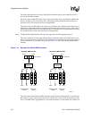
Depending on the type of panel used, the LCD controller is programmed to use either 4-, 8-, or
16-pixel data output pins. Single-panel monochrome displays use either four or eight data pins to
output 4 or 8 pixels for each pixel clock; single-panel color displays use eight pins to output 2-2/3
pixels each pixel clock (8 pins / 3 colors/pixel = 2-2/3 pixels per clock). The LCD controller also
supports dual-panel mode, which causes the LCD controller’s data lines to be split into two groups,
one to drive the top half and one to drive the bottom half of the screen. For dual-panel displays, the
number of pixel data output pins is doubled, allowing twice as many pixels to be output each pixel
clock to the two halves of the screen.
In active color display mode, the LCD controller can drive TFT displays. The LCD’s line clock pin
functions as a horizontal sync (HSYNC) signal, the frame clock pin functions as a vertical sync
(VSYNC) signal, and the ac bias pin functions as an output enable (OE) signal. In TFT mode, the LCD’s
dither logic is bypassed, sending selected palette entries (12 bits each) directly to the LCD’s data output
pins. Additionally, 16-bit pixels can be used that bypass both the palette and the dither logic.
The LCD controller can be configured in active color display mode and used with an external DAC
(and optionally an external palette) to drive a video monitor. Note that only monitors that implement
the RGB data format can be used; the LCD controller does not support the NTSC standard.