


226 SA-1110 Developer’s Manual
Peripheral Control Module
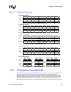
11.7.1.3 Input FIFO
Data from the LCD’s DMA is directed either to the palette or the input FIFO. The direction of data
flow is switched whenever the LCD controller is first enabled and by each frame pulse. After the
LCD controller is configured and enabled, the first 32 (4-, 12-, and 16-bits/pixel) or 512
(8-bit/pixel) bytes supplied by the DMA are sent to the palette. All subsequent encoded pixel data
is sent to the FIFO. After an entire frame of pixels has been processed, the frame clock pin is
pulsed to denote the start of the next frame. This signal is also used to change the direction of DMA
input data from the FIFO back to the palette. A modulus of 8 (4-, 12-, and 16-bits/pixel) or 128
(8-bits/pixel) is used to count when loading the palette RAM, depending on the pixel bit size shown
above. A 7-bit counter is loaded each time a frame clock pulse occurs or the LCD is enabled, and is
decremented each time a word is stored to the palette (two palette entries). When the counter wraps
around to zero, the data input from the DMA is switched back to the FIFO.
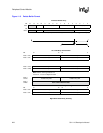
The LCD controller contains a 5-entry x 32-bit wide input FIFO that is used to store encoded pixels
fetched from the frame buffer. The FIFO signals a service request to the DMA whenever four
entries of the FIFO are empty. In turn, the DMA automatically fills the FIFO with a 4-word burst.
Pixel data from the frame buffer remains packed within individual 32-bit words when it is loaded
into the FIFO. The LCD controller’s port size is 32 bits wide to accommodate the heavy data flow
from the frame buffer. Depending on the number of bits per pixel, as words are taken from the
bottom of the FIFO, they are unpacked and supplied to the lookup palette in nibbles (4 bits/pixel)
or bytes (8 bits/pixel) to the dither logic (12 bits/pixel), or directly to the pins in half-word
increments (16 bits/pixel).
Each time a word is taken from the bottom of the FIFO, the entry is invalidated and all data in the
FIFO moves down one position. When four entries are empty, a service request is issued to the DMA.
11.7.1.4 Lookup Palette
The encoded pixel data taken from the bottom entry of the input FIFO is used as an address to
index and select individual palette locations. Four-bit pixel encodings address 16 locations and
8-bit pixel encodings select any of the 256 palette entries. Note that the user may program 1, 2, and
3 bits/pixel as well by zeroing out the upper 3, 2 or 1 bits of each encoded pixel value in the frame
buffer, respectively. However, for 1, 2, and 3 bits/pixel, the encoded pixel size remains at 4 bits
within the frame buffer and within the LCD controller’s input FIFO.
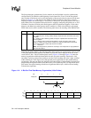
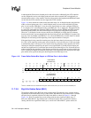
Once a palette entry is selected by the encoded pixel value, the contents of the entry is sent to the
color/gray-scale space/time base dither circuit. In color mode, the value within the palette is made up
of three 4-bit fields, one for each color component – red, green, and blue. In monochrome mode, only
one 4-bit value is present (see Figure 11-3). For both modes, the 4-bit values represent one of 15
intensity levels. For color operation, an individual frame is limited to a selection of 256 colors (the
number of palette entries). However, the LCD controller is capable of generating a total of 3375
colors (15 levels per color ^ 3 colors = 3375). When 12 or 16 bits per pixel mode is enabled, the
palette is bypassed. For passive displays, 12-bit pixels are sent directly to the dither logic; for active
displays, 16-bit pixels are sent to the output FIFO to be driven directly to the LCD’s data pins.
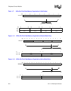
11.7.1.5 Color/Gray-Scale Dithering
For passive displays, entries selected from the lookup palette are sent to the color/gray-scale
space/time base dither generator. Each 4-bit value is used to select one of 15 intensity levels. Note
that two of the 16 dither values are identical (always high). The color/gray intensity is controlled by
turning individual pixels on and off at varying periodic rates. For some screens, more intense
colors/grays are produced by making the average time the pixel is high longer than the average