


SA-1110 Developer’s Manual 437
32.768–KHz Oscillator Specifications C
A 32.768-kHz crystal oscillator is integrated on the Intel
®
StrongARM
*
SA-1110 Microprocessor
(SA-1110) for use as a time base for the real-time clock (RTC). The output frequency of the crystal
oscillator is divided by 32768 (2
15
) to deliver a 1-Hz signal to the RTC. A digital tuning circuit is
included on the SA-1110 to calibrate the 1-Hz output for each crystal and circuit based on a set of
values stored in an external EEPROM. The oscillator circuit is designed to work across a range of
crystal parameters so that the system designer can choose from several 32.768-kHz crystals available
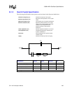
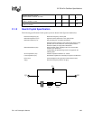
on the market. In normal operation, the pins of the crystal, Q1 and Q2, are connected to the SA-1110
pins, TXTAL and TEXTAL.
In some applications, it may be desirable to provide the 32.768-kHz reference from an external
signal source. This option is supported by the SA-1110. See the Chapter 8, “Clocks”.
C.1 Specifications
This section includes specifications for the oscillator circuit and the quartz crystal.
C.1.1 System Specifications
This section includes the specifications of the oscillator circuit. It assumes that the crystal used
meets the specifications given in the following sections.
C.1.1.1. Temperature Range
This is the junction temperature range for the oscillator circuit on the SA-1110. The crystal itself
may be at the ambient temperature; the oscillator circuit integrated on the SA-1110 is most likely
operating at a higher temperature that is dependent on the activity of the SA-1110.
C.1.1.2. Current Consumption
Because this oscillator runs during the sleep mode of the processor, the power consumption is
critical. The specified current consumption is for the oscillator and its output buffer only. The
power of the tuning circuit and RTC is not included in the value specified.
C.1.1.3. Startup Time
This specification depends on the crystal characteristics and the layout of the printed circuit board
(PCB). The value given assumes that the crystal and board layout conform to the values given in
the remainder of this document. The critical parameters in the crystal specification are the shunt
capacitance (Co) and the motional resistance (Rm), which must be no greater than the maximums
specified. The critical parameters in the PCB layout are the parasitic capacitances between TXTAL
and TEXTAL, and between either of these nodes and VSS. Note that in some applications, such as
a system that includes a socketed SA-1110, it may be difficult to meet the parasitic capacitances
specified.