


SA-1110 Developer’s Manual 261
Peripheral Control Module
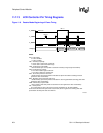
11.8.1 USB Operation
Following either a reset of the SA-1110 or whenever a USB cable is connected to the SA-1110
UDC, the SA-1110 UDC automatically configures all of its Endpoints and forces itself to use the
USB default address of zero. The Host then assigns a unique address to the SA-1110 UDC. At this
point, the SA-1110 UDC is under the Host’s control, i.e., the SA-1110 UDC responds to commands
(control transactions) that are transmitted by the Host to the SA-1110 UDC’s Endpoint 0. The Host
transmits “Bulk OUT” Data Frames to the SA-1110 UDC’s Endpoint 1; the Host receives “Bulk
IN”DataFramesfromtheSA-1110UDC’sEndpoint2.
Note: The SA-1110 UDC cannot be powered by the USB cable alone. According to Section 7.2.3 of the
USB Specification, Version 1.1
1
, a USB client device (SA-1110 UDC) is required to consume less
than 500 uA after receiving a Suspend signal from the Host. The SA-1110 UDC cannot limit its
current consumption to 500 uA unless the SA-1110 enters sleep mode. However, when the
SA-1110 enters sleep mode, all of its SA-1110 UDC registers are reset and the SA-1110 UDC will
no longer respond to the Host–assigned address.
Note: The SA-1110 UDC must only describe one device configuration to the Host during the
GET_DESCRIPTOR phase of the Host’s interrogation of the SA-1110 UDC. If multiple device
configurations were to be described to the Host and if the Host then signals a switch to a different
device configuration, the SA-1110 UDC would be required to flush any data that is in the TX
FIFO. In order for the SA-1110 UDC to flush the TX FIFO, the SA-1110 UDC must first be
disabled. Consequently, when the SA-1110 UDC is re-enabled, all of its registers will be reset and
the SA-1110 UDC will no longer respond to the Host–assigned address.
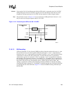
11.8.1.1 Signalling Levels
USB uses differential signalling to encode data and to communicate various bus conditions. The
USB Specification refers to the J and K data states to differentiate between high- and low-speed
transmission. Because the SA-1110 UDC supports only 12-Mbps High Speed mode transmission,
references are made only to actual data states 0 and 1.
With differential signaling, four distinct states are represented by decoding the polarity of the
UDC+ and UDC- pins. Two of the four states are used to represent data. A “one” is represented
when UDC+ is high and UDC- is low; a “zero” is represented when UDC+ is low and UDC- is
high. The remaining two of the four states along with voltage and/or timing permutations of the
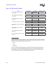
four encodings are decoded to provide five additional states. So, seven states are provided for the
USB bus as shown in Table 11-11.
1. Access the most recent revision of the Universal Serial Bus Specification via the World Wide Web at:
http://www.usb.org/developers/docs.html
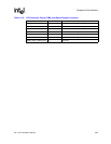
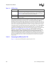
Table 11-11. USB Bus States
Bus State UDC+/UDC- Pin Levels
Idle
UDC+ high, UDC- low (same as a 1).
Resume
UDC+ low, UDC- high (same as a 0).
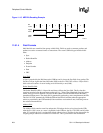
StartofPacket
Transition from idle to resume.
End of Packet
UDC+ AND UDC- low for 2-bit times followed by an idle for 1-bit time.