


SA-1110 Developer’s Manual 73
System Control Module 9
This chapter describes the system control module that controls several processor-wide system
functions. The units contained in the system control module are: the general-purpose I/O ports, the
interrupt controller, the real-time clock, the operating system timer, the power manager, and the
reset controller.
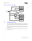
9.1 General-Purpose I/O
The Intel
®
StrongARM
*
SA-1110 Microprocessor (SA-1110) provides 28 general-purpose I/O
(GPIO) port pins for use in generating and capturing application-specific input and output signals.
Each pin is programmable as an input or output and as an interrupt source. All 28 pins are
configured as inputs during the assertion of reset, and remain inputs until they are configured
otherwise.
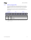
Each GPIO pin can be configured as an input or an output by programming the GPIO pin direction
register (GPDR). When programmed as an output, the pin can be controlled by writing to the GPIO
pin output set register (GPSR) and the GPIO pin output clear register (GPCR). Writing to these
registers controls the output data register, which is not directly readable or writable. The set and
clear registers can be written regardless of whether the pin is configured as an input or an output.
The programmed output state will take effect when the pin is reconfigured as an output.
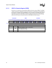
When programmed as an input, the current state of each GPIO pin can be read through the GPIO
pin-level register (GPLR). This register can be read at any time and can be used to confirm the state
of the pin when it is configured as an output. In addition, each GPIO pin can be programmed to
detect a rising and/or falling edge through the GPIO rising-edge detect register (GRER) and GPIO
falling-edge detect register (GFER). The state of the edge detect can be read through the GPIO
edge detect status register (GEDR). These edge detects can be programmed to generate an interrupt
(see the Section 9.2, “Interrupt Controller” on page 9-83) or to serve as a wake-up event to bring
the SA-1110 out of sleep mode (see the Section 9.5, “Power Manager” on page 9-99).
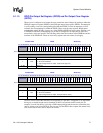
When the SA-1110 enters sleep mode, the contents of the power manager sleep state register
(PGSR) is loaded into the output data register. If the particular pin is programmed as an output,
then the state in the PGSR will be driven onto the pin before entering sleep. When the SA-1110
exits sleep mode, these values remain until reprogrammed by writing to the GPSR and GPCR.
Some GPIO pins can also serve an alternate function within the SA-1110. Certain modes within the
serial controllers and LCD controller require extra pins. These functions are hard–wired into
specific GPIO pins. How these functions are used is described in the following sections. Even
though a GPIO pin has been taken over for an alternate function, you must still program the correct
direction of that pin through the GPDR. Details on alternate functions are also provided in
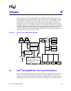
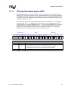
following sections. Figure 9-1 shows a block diagram of a single GPIO pin.