


288 SA-1110 Developer’s Manual
Peripheral Control Module
11.8.8.3 Receive Packet Error (RPE)
The RPE bit is automatically set to 1 after the detection of either a CRC, bit stuffing, DATA toggle
mismatch, or FIFO overrun error. The RPE bit is only valid if the RPC bit is set to 1. The RPE bit is
cleared by the CPU writing a 1 to the RPC bit.
11.8.8.4 Sent Stall (SST)
The SST bit is automatically set to 1 when the SA-1110 UDC issues a STALL Handshake (due to a
protocol violation where the Host sends more data than the maximum packet size) to abort the
current transfer. The SST bit is cleared by the CPU writing a 1 to it.
11.8.8.5 Force Stall (FST)
The FST bit can be set to 1 by the SA-1110 UDC to force STALL Handshakes to be issued to all
OUT Tokens. STALL Handshakes will continue to be sent to the Host until the CPU clears the FST
bit by writing a 0 to it. The SST bit will be automatically set to 1 when the STALL state is actually
entered (this may be delayed if the SA-1110 UDC is active when the FST bit is set). The STALL
state will not be exited until both the FST and SST bits are cleared by the CPU writing a 1 to each
of them.
When the Host sends a command, such as ClearFeature(HALT), the SA-1110 UDC is required to
reinitialize its internal data toggle flag back to DATA0. To reinitialize this flag, the CPU must:
1. Set the FST bit by writing a 1 to it and read it back to ensure it is set.
2. Clear the FST bit by writing a 0 to it and read it back to ensure it is cleared.
3. Clear the SST bit by writing a 1 to it and read it back to ensure it is cleared.
11.8.8.6 Receive FIFO Not Empty (RNE)
The RNE bit indicates that there is unread data in the Receive Data FIFO. The RNE bit must be
polled when the RPC bit is set to determine if there is any data in the Receive Data FIFO that DMA
did not remove. To ensure that lingering data will not be lost, the Receive Data FIFO must continue
to be read until the RNE bit is automatically cleared to 0.
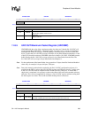
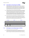
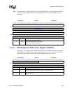
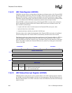
11.8.9 UDC Endpoint 2 Control/Status Register (UDCCS2)
UDCCS2 contains 6 bits that are used to operate Endpoint 2 (IN Endpoint).
Note: Due to the internal synchronization required by the SA-1110 UDC configuration registers, it is
possible for the CPU to write to the SA-1110 UDC registers and FIFOs too fast. So, a single write
to the SA-1110 UDC must be completed before another write may take place. To ensure that a
single write is completed, it is necessary to observe the effect of the write before another write may
take place. This can be accomplished by writing to a SA-1110 UDC register and then reading back
the same register two times. The second read-back should produce correct data.