


98 SA-1110 Developer’s Manual
System Control Module
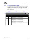
9.4.5 OS Timer Interrupt Enable Register (OIER)
This register contains four enable bits indicating whether a match between one of the match
registers and the OS timer counter will set a status bit in the OSSR. Each match register has a
corresponding enable bit. Clearing an enable bit does not clear the corresponding interrupt status
bit if that bit is already set.
9.4.6 Watchdog Timer
OSMR 3 may also serve as a watchdog compare register. This function is enabled by setting bit 0 in
the OWER. When a compare against this register occurs and the watchdog is enabled
(OWER:WME=1 and OIER:E3=1), reset is applied to the SA-1110 and most internal states are
cleared (with exceptions listed below). Internal reset is asserted for 256 processor clocks and then
removed, allowing the SA-1110 to boot. Units that do not receive this internal reset are: the power
manager, the refresh timer, and the PLL configuration. Watchdog reset affects the SA-1110 similar
to a software reset. See the Section 9.6, “Reset Controller” on page 9-115 for details on what is
affected by each kind of reset. When the SA-1110 comes out of a watchdog reset, a bit is set in the
reset controller status register (RCSR) to indicate that the event happened.
The user must clear OSSR:M3 before setting up a watchdog reset. The following procedure is
suggested when using OSMR 3 as a watchdog: each time the operating system services the register,
the current value of the counter is read, and a number is then added to the value read,
corresponding to the amount of time before the next time-out (care must be taken to account for
counter wrap–around). This number is then written back to OSMR 3. The OS code must repeat this
procedure periodically before each match occurs. If the match occurs, the OS timer will assert a
reset.
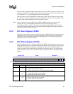
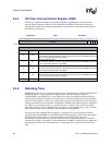
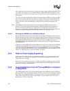
0h 9000 001C OIER Read/Write
31 30 29 28 27 26 25 24 23 22 21 20 19 18 17 16 15 14 13 12 11 10 9 8 7 6 5 4 3 2 1 0
Reserved
E3
E2
E1
E0
Reset 0 0 0 0 0 0 0 0 0 0 0 0 0 0 0 0 0 0 0 0 0 0 0 0 0 0 0 0 0 0 0 0
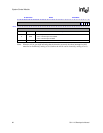
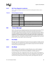
Bits Name Description
0E0
Interrupt enable channel 0.
This bit is set by software and allows a match between match register OSMR[0] and the OS
timer to assert interrupt bit M0 in the OSSR.
1E1
Interrupt enable channel 1.
This bit is set by software and allows a match between match register OSMR[1] and the OS
timer to assert interrupt bit M1 in the OSSR.
2E2
Interrupt enable channel 2.
This bit is set by software and allows a match between match register OSMR[2] and the OS
timer to assert interrupt bit M2 in the OSSR.
3E3
Interrupt enable channel 3.
This bit is set by software and allows a match between match register OSMR[3] and the OS
timer to assert interrupt bit M3 in the OSSR.
31..4 — Reserved