


SA-1110 Developer’s Manual 327
Peripheral Control Module
11.11.1.4 Transmit Operation
The UART transmit logic operates at the same time as the receive logic (full-duplex). Data is taken
from the transmit FIFO; start, parity, and stop bits are added to generate a frame; and the value is
loaded into a serial shift register. The contents are shifted out onto the TXD3 pin, clocked by the
programmed baud clock. When the transmit FIFO is emptied more than halfway, an interrupt or
DMA request is signalled. If the transmit FIFO is completely emptied, the transmit line remains
high (one) after the last data value is transmitted to indicate the transmitter is idle. The TXD3 pin
remains high until additional data is written to the transmit FIFO.
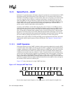
11.11.1.5 Transmit and Receive FIFOs
To reduce chip size and power consumption, the UART’s FIFOs use self-timed logic (they are not
clocked). Because of process and environmental variations, the depth at which a service request is
triggered to empty the receive FIFO is variable. This variation spans a maximum of four FIFO
entries; the receive FIFO service request can be made at four different FIFO depths.To compensate
for this variability and guarantee that at least four valid entries of data exist within the FIFO before
generating a service request, an extra four entries have been added to the receive FIFO (four entries
more than the transmit FIFO). The transmit FIFO is 8 entries deep and the receive FIFO is 12
entries deep. The point at which the receive FIFO service request is triggered spans the middle
third of the 12-entry FIFO. The service request is signalled at a depth from one-third full to
two-thirds full (when the FIFO contains five, six, seven, or eight entries of data).
This service request variation applies only to an empty FIFO that is filled (receive FIFO). It does
not apply to a full FIFO that is emptied (transmit FIFO). The transmit FIFO is guaranteed to signal
a service request when it has four or more empty entries and negate the request when the FIFO
contains five or more entries that are filled.
If the DMA is used to service either one or both of the UART’s FIFOs, the burst size must be set to
4 words even though more than four entries of data may exist within the receive FIFO. If
programmed I/O is used to service the FIFOs, a maximum of 4 words may be added to the transmit
FIFO without checking if more space is available. Likewise, a maximum of 4 words may be
removed from the receive FIFO without checking if more data is available. After this point, the
user must poll a set of status bits that indicates if any data remains in the receive FIFO or if space is
available in the transmit FIFO before emptying or filling the FIFOs any further.
11.11.1.6 CPU and DMA Register Access Sizes
Bit positioning, byte ordering, and addressing of the UART is described in terms of little endian
ordering. All UART registers are 8 bits wide and are located in the least significant byte of
individual words. The ARM peripheral bus does not support byte or half-word operations. All
reads and writes of the UART by the CPU should be word–wide. Two separate dedicated DMA
requests exist for both the transmit and the receive FIFO. If the DMA controller is used to service
the transmit and/or receive FIFOs, the user must ensure the DMA is properly configured to perform
byte–wide accesses, using 4 bytes per burst.
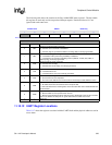
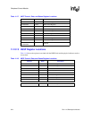
11.11.2 UART Register Definitions
There are seven byte–wide registers within the UART: four control registers, one data register, and
two status registers. The control registers are used to program the baud rate, data length, number of
stop bits, and odd or even parity. They are used to receive and transmit sample clock edge type, and
to transmit a break. Also, they are used to enable or disable transmit and receive operation, parity,