


SA-1110 Developer’s Manual 93
System Control Module
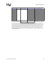
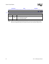
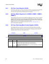
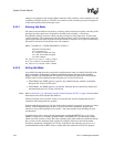
9.3.4 RTC Trim Register (RTTR)
Program the RTTR to select the frequency of the Real Time Clock (RTC). If this register is not
programmed and left at its reset value (all zeros), then the RTC will actually be running at 32.768
kHz. Refer to Section 9.5.7.8, “Power Manager Oscillator Status Register (POSR)” on page 9-114
to understand when the Real Time Clock is stable. Refer to Section 9.3.5.2, “RTTR Value
Calculations” on page 9-94 for details on how to calculate the value of the RTTR. The following
table shows the location of all bits in the RTTR. All reserved bits are read as zeros and are
unaffected by writes.
9.3.5 Trim Procedure
The 1-Hz clock feeding the RTC is obtained by dividing the output of the 32.768-kHz oscillator
down. Since 32768 is a power of two, a 15-bit divider will generate a 1-Hz clock (given a perfect
crystal and perfect board environment). The inherent inaccuracies of crystals, aggravated by
varying capacitance of the board connections, and so on, cause the timebase to be somewhat
inaccurate, requiring a periodic adjustment in the 1 Hz clock period. The SA-1110, through the
RTTR, allows the user to adjust or "trim" the 1 Hz timebase to an accuracy of +/- 5 seconds per
month. At reset, the RTTR contains zeros that disable the trim circuitry. When the trim circuitry is
disabled, the 1-Hz clock feeding the RTC is the same frequency as the output of the 32.768-kHz
oscillator. The RTTR is reset to all zeros each time the nRESET signal is asserted.
9.3.5.1 Oscillator Frequency Calibration
To generate the value to be entered into the RTTR, the user must first measure the output frequency
of the 32.768-kHz oscillator using an accurate timebase, such as a frequency counter. This clock is
made externally visible by selecting the alternate function for GPIO 27. To gain access to the clock,
this pin must be programmed as an output and then switched over to the alternate function. See the
Section 9.1, “General-Purpose I/O” on page 9-73 in this chapter for details on how to gain access
to the clock. The trim is accomplished by dividing the output of the oscillator by an integer value
and then doing fine-grain fractional adjustment by periodically deleting clocks from the stream
feeding this integer divider.
0h 9001 0008 RTTR Read/Write
31 30 29 28 27 26 25 24 23 22 21 20 19 18 17 16 15 14 13 12 11 10 9 8 7 6 5 4 3 2 1 0
Reserved Trim Delete Count Clock Divider Count
Reset
0 0 0 0 0 0 0 0 0 0 0 0 0 0 0 0 0 0 0 0 0 0 0 0 0 0 0 0 0 0 0 0
Bits Name Description
15..0 C15..C0
Clock divider count.
This value is the integer portion of the clock trim logic.
25..16 D9..D0
Trim delete count.
This value represents the number of 32-kHz clocks to delete when clock trimming begins.
31..26 — Reserved