


16 SA-1110 Developer’s Manual
C.1.1.8. Parasitic Resistance Between TXTAL or TEXTAL and VSS .........................438
C.1.2 Quartz Crystal Specification .........................................................................................439
D Internal Test
D.1 Test Unit Control Register (TUCR) ...........................................................................................441
Figures
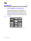
1-1 SA-1110 Features ......................................................................................................................21
1-2 SA-1110 Example System..........................................................................................................25
2-1 SA-1110 Block Diagram ............................................................................................................. 30
2-2 SA-1110 Functional Diagram .....................................................................................................31
2-3 SA-1110 Memory Map................................................................................................................38
6-1 Format of Internal Coprocessor Instructions MRC and MCR .....................................................55
8-1 SA-1110 Clock System Block Diagram ......................................................................................69
9-1 General-Purpose I/O Block Diagram ..........................................................................................74
9-2 Interrupt Controller Block Diagram ............................................................................................. 83
9-3 Transitions Between Modes of Operation ................................................................................105
10-1 General Memory Interface Configuration ................................................................................. 120
10-2 Memory Pins and Memory Controller State after Hardware Reset .........................................124
10-3 DRAM Single-Beat Transactions..............................................................................................151
10-4 Dram Burst-of-Eight Transactions ............................................................................................152
10-5 SDRAM State Machine.............................................................................................................156
10-6 SDRAM 1-Beat Read/Write/Read Timing for 4 Bank x 4 M x 4 Bit
Organization (64 Mbit) ..............................................................................................................157
10-7 SDRAM 1-Beat Read/Write Timing for 4 Bank x 4 M x 4 Bit Organization
(64 Mbit) at Half-Memory Clock Frequency (MDREFR:KnDB2=1)) .........................................158
10-8 SDRAM 8-Beat Read/Write Timing for 4 Bank x 4 M x 4 Bit
Organization (64 Mbit) ..............................................................................................................159
10-9 DRAM/SDRAM CBR Refresh Cycle.........................................................................................161
10-10 Burst-of-Eight ROM or Flash Read Timing Diagram ................................................................164
10-11 Eight-Beat Burst Read from Burst-of-Four ROM or Flash ........................................................165
10-12 Nonburst ROM, SRAM, or Flash Read Timing Diagram – Four Data Beats)...........................166
10-13 SRAM Write Timing Diagram (4–Beat Burst) ...........................................................................168
10-14 Variable Latency I/O Read Timing (Burst-of-Four) ...................................................................170
10-15 Variable Latency I/O Write Timing (Burst-of-Four) ...................................................................171
10-16 Flash Write Timing Diagram (2 Writes) ....................................................................................173
10-17 SMROM State Machine............................................................................................................ 176
10-18 SMROM Eight-Beat and Two-Beat Timing for 2 M x 16 Bit Organization
(32 Mbit) at Half-Memory Clock Frequency (MDREFR:K0DB2=1)...........................................177
10-19 PC-Card Memory Map..............................................................................................................178
10-20 PC-Card External Logic for a Two-Socket Configuration .........................................................181
10-21 PC-Card External Logic for a One-Socket Configuration .........................................................182
10-22 PC-Card Memory or I/O 16-Bit Access.....................................................................................183
10-23 PC-Card I/O 16-Bit Access to 8-Bit Device ..............................................................................184
10-24 DRAM System Example ...........................................................................................................187
10-25 SDRAM System Example.........................................................................................................188